


LA000577C © 2006 Navman New Zealand. All rights reserved. Proprietary information and specications subject to change without notice.
7
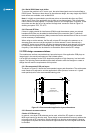
2.3.3 Solder paste mask size
This should be adjusted by experimentation according to the customer’s production process
requirements. A 1:1 (paste mask:pad size) ratio has been found to be successful.
2.3.4 Solder paste type
The module accepts all commonly used solder pastes. The solder paste can be lead based
or lead-free. If a lead-free process is introduced, factors such as circuit board thickness,
fabrication complexity, assembly process compatibility, and surface nish should be taken
into consideration.
2.3.5 Coating
The nal PCB may be selectively coated with an acrylic resin, air/oven cured conformal
coating, clear lacquer or corresponding method, which gives electrical insulation and
sufcient resistance to corrosion.
2.3.6 Post reow washing
It is recommended that a low residue solder paste is used to prevent the need for post reow
washing. If a washing process is used, an aqueous wash is not recommended due to the
long drying time required and danger of contaminating the ne pitch internal components.
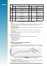
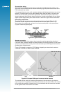
2.3.7 Pre-baking
The modules are delivered on a tape and reel package sealed in an airtight bag. The MSR
(Moisture Sensitivity Rating) is 3, therefore they should be loaded and reowed within
168 hours. If the modules are in ambient humidity for longer than this, a pre-baking/drying
process will be required.
2.3.8 Rework
Navman recommends that rework and repair is carried out in accordance with the following
guidelines:
• IPC-7711 Rework of Electronic Assemblies
• IPC-7721 Repair and Modication of Printed Boards and Electronic Assemblies
Note: Jupiter 30 and Jupiter 20 modules are covered by a 12-month warranty.
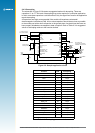
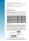
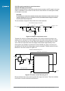
2.4 Typical application circuit
The schematic in Figure 2-2 represents a very basic application circuit, with simple interfaces to
the module. It is subject to variations depending on application requirements.
Note: Refer to the Jupiter 20 Dead Reckoning Application Note (LA000433) for the Jupiter 20 D
reference design.
2.4.1 Power for receiver and active antenna
The receiver power connection requires a clean 3.3 VDC. Noise on this line may affect the
performance of the GPS receiver.
When an active antenna is used, the DC power is fed to it through the antenna coax. This
requires the user to apply the antenna DC voltage to pad 19 of the module. A 2.7 V 25 mA
supply is made available on pad 20 if the chosen antenna can accept that voltage. This
supply is under the command of the TricklePower energy control.
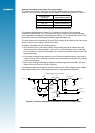
2.4.2 Grounding
Separate AGND (Analogue Ground) and DGND (Digital Ground) grounds are shown
in Figure 2-2. If this grounding method is used, the ground planes can be connected
underneath the module. In some applications with very small ground planes, separate ground
planes may not be required. This should be determined by the application integrator. See
Section 2.5.2 for ground plane recommendations and design considerations involving the
antenna input and the 50 Ω microstrip connection.