


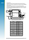
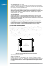
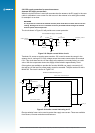
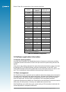

FR4 breglass PCB
passive patch antenna
Jupiter module
50 ohm microstrip
ground plane ground via
LA000577C © 2006 Navman New Zealand. All rights reserved. Proprietary information and specications subject to change without notice.
13
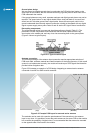
2.6.3 Passive antenna
A passive antenna does not require any power because it has no amplier. This is not the
best choice if signal strength is a concern, however, it may be sufcient if the signal path is
kept to a minimum (usually below 300 mm). An advantage to using a passive antenna is the
ability to mount directly onto the application. For best performance, a passive patch antenna
should have a metal ground plane (about 80 mm in diameter) placed directly under the
antenna, and it is advisable to screen the module and application circuits from the antenna.
For this reason the antenna and module should not be mounted on the same side of the PCB
(see Figure 2-8).
Figure 2-8: Cross section of application board with passive patch antenna
Any cover close to the antenna (called the superstrate) will cause the resonant frequency and
efciency of the antenna to drop. It is therefore recommended to keep any distance to the
superstrate to a minimum of 3 mm from the top surface of the patch.
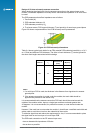
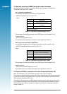
See Table 2-6 for recommended characteristics of both passive patch and active antennas
for use with the Jupiter receiver.
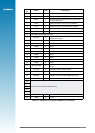
Characteristic Active antenna Passive antenna
Polarisation
right-hand circular polarised right-hand circular polarised
Receive frequency
1.57542 GHz
+/- 1.023 MHz
1.57542 GHz
> +/- 1.023 MHz
Power supply 3 V –
DC current < 10mA at 3 VDC –
Antenna gain
–
+2 to 5 dBi with 1 dB loss (max)
in connections
Total gain (includes
antenna gain, LNA
gain and cable loss)
≤ 26 dBi (Jupiter 20)
≤18 dBi (Jupiter 30)
–
Axial ratio < 3 dB < 3 dB
Output VSWR
< 2.5
–
Table 2-6: Recommended antenna characteristics
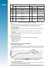
Note: GPS active and passive antenna selection must include practical TTFF tests
in weak and strong outdoor environments – noting peak and average signal strength
measurements. This must be done in comparison with the antenna supplied in the
Development kit. Performance results and signal strength measurements must be
comparable to the reference antenna supplied. Passive antenna signal strength
measurements will be lower than an active antenna, but time to x should be comparable.
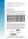
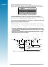
2.6.4 Jupiter module used as a GPS sensor
The adapter board reference design shows how a Jupiter GPS receiver module can be used
with an external active antenna via a coax connector. The same design can be used with
a passive patch antenna on the same PCB. It follows the general arrangement described
in Section 2.6.3. The module is placed such that the connection between the antenna and
the antenna input pad is as short as possible. Also note the PCB should have a complete
ground plane on the patch side of the board. This serves as the ground plane required by the
antenna.
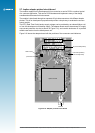
The serial data from the module must be connected to a local host processor, and care
should be taken such that noise from these devices cannot enter the signal path or GPS
antenna. It is recommended that all digital devices are placed on the opposite side of the
board to that of the antenna.