


LA000577C © 2006 Navman New Zealand. All rights reserved. Proprietary information and specications subject to change without notice.
17
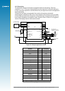
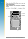
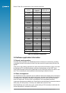
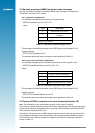
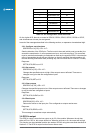
Refer to Table 2-8 for a description of the connector interfaces.
Jupiter
function
J2 (2.54 mm
pitch header)
pin no.
J1 (2 mm pitch
header) pin no.
V_ANT 1 1
VCC_RF 2 –
V_BATT 3 3
VDD 4 4
M_RST 5 5
GPIO/GYRO IN 6 6
GPIO/FR 7 7
BOOT 8 8
GPIO/W TICKS 9 9
RFON 10 –
GND – 10
TXA 11 11
RXA 12 12
GPIO/SDI 13 –
GND – 13
TXB 14 14
RXB 15 15
GPIO/SCK 16* –
GND 17 16
GPIO/SDO 18 –
GND – 17
GND – 18
1PPS 19 19
GPS_FIX/GPIO 20 –
*Note: J2 Pin 16 on the adapter card is the wake-up line for
push to x mode on the Jupiter 30
Table 2-8: Connector conguration
3.0 Software application information
3.1 Normal mode operation
In normal mode of operation, the baseband processor software runs continuously, providing
a navigation solution at the maximum rate of once per second. No power saving functions are
applied.
If the power to the module is disrupted, the restart time can be shortened to a warm or hot start
by keeping the RTC and SRAM contents valid with a backup battery on the VBATT input.
If the module has been turned off for greater than 2 hours, the unit will revert to a warm or cold
start. This is caused by the stored ephemeris data becoming invalid after 4 hours.
3.2 Power management
The TricklePower mode of operation can be enabled to reduce the average power consumption.
The main power is supplied to the module continuously. An internal timer wakes the processor
from sleep mode. The module computes a navigation position x, after which the processor
reverts to sleep mode. The duty cycle is controlled by a user-congurable parameter.
If ephemeris data becomes outdated, the TricklePower mode will attempt to refresh the data set
within every 30 minute period, or for every new satellite that comes into view.
With TricklePower set to a 20% duty cycle, a power saving of 50% can easily be achieved with
minimal degradation in navigation performance.