


LA000577C © 2006 Navman New Zealand. All rights reserved. Proprietary information and specications subject to change without notice.
6
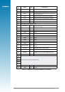
Pin
Jupiter 30 Jupiter 20
GPIO Name and Description GPIO
Standard &
XTrac name
DR function
24 13 reserved 6 GPIO (SDO) not connected
25 4 reserved 5 GPIO (SDI) ADC DOut
26 –
WAKEUP
push-to-x wakeup (active on +ve edge)
7 GPIO (SCK) ADC Clk
27 15
ANT_OC
antenna open circuit sensor input (active
high)
15 ANT_OC
FWD/REV
fwd/rev input
(low=forward,
high=reverse)
28 1
ANT_CTRL
active antenna control output
1 ANT_CTRL
WHEEL_TICKS
wheel tick input
8 14
NANT_SC
antenna short circuit sensor input (active
low)
3 NANT_SC
GYRO_IN
gyro input
(analogue 0–5 V)
Table 2-2: Summary of pin multi-functionality
GPIO
Note that the Jupiter 20 D (Dead Reckoning) does not support the active antenna supervisory
functionality and associated proprietary NMEA status messaging (see section 3.7).
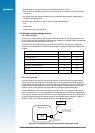
SPI (Jupiter 20 only)
The Jupiter 20 (GSW2) and Jupiter 20 S (XTrac) do not support the SPI. These pins function
only as user GPIOs.
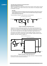
The SPI on the Jupiter 20 D is used to control an internal ADC, which interfaces to an
external gyro.
Implementation of the SPI for any other alternative function requires an SDK (Software
Development Kit) from SiRF.
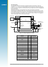
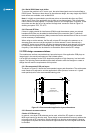
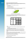
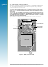
2.2 Physical dimensions
The physical dimensions of the Jupiter 30 and Jupiter 20 modules are identical:
length: 25.4 mm ± 0.1 mm
width: 25.4 mm ± 0.1 mm
thickness: 3.0 mm max
weight: 4.0 g max
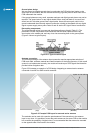
2.3 Manufacturing process recommendations
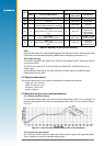
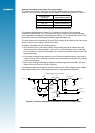
2.3.1 Reow recommendations
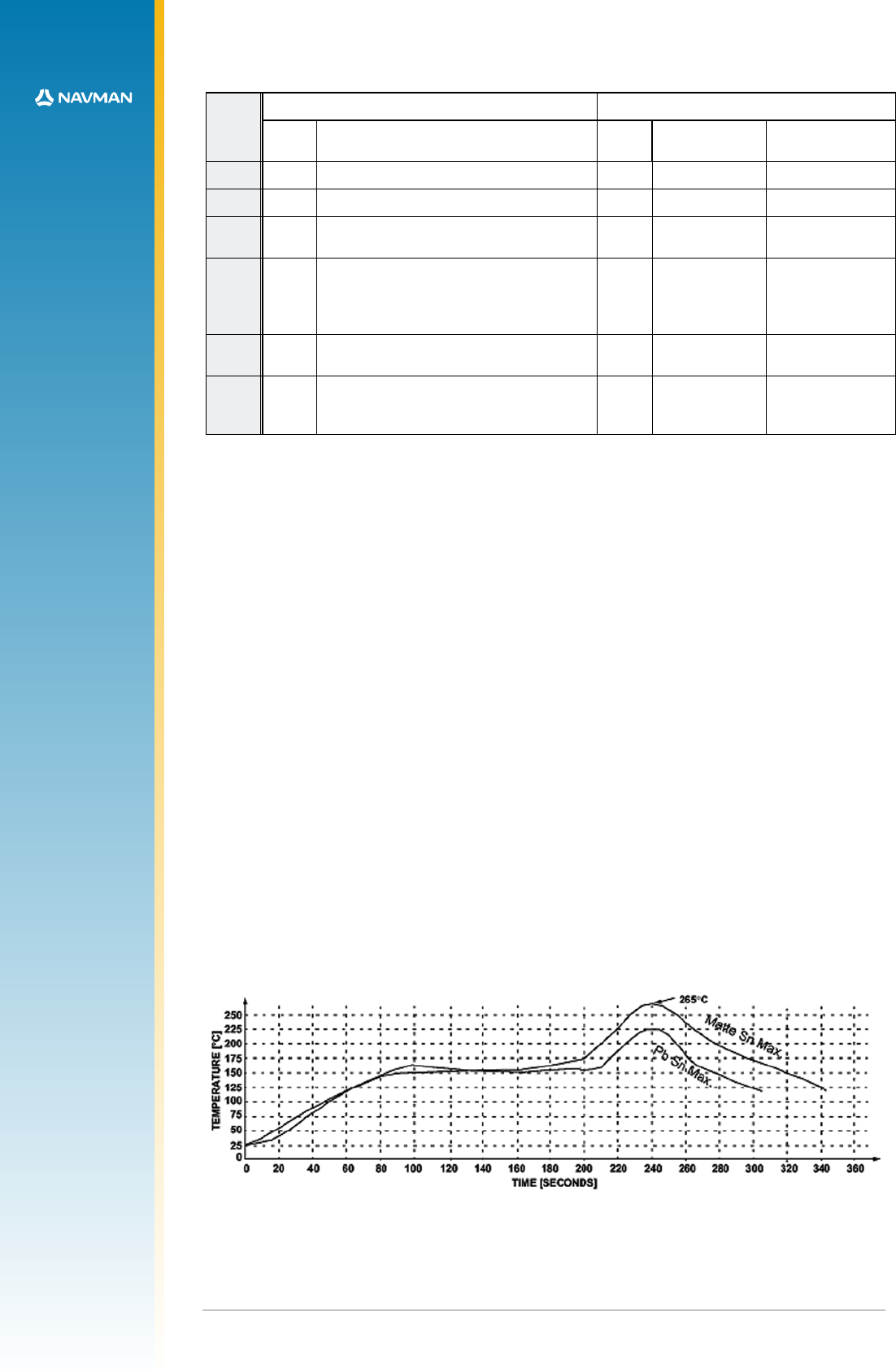
For lead based solder pastes, the maximum reow temperature is 225 °C for 10 seconds. For
lead-free solder pastes, the maximum reow temperature is 265 °C for 10 seconds. Refer to
Figure 2-1.
Figure 2-1: Lead-free and tin/lead reow prole recommendation
2.3.2 Connection pad material
The 30 surface mount connection pads have a base metal of copper with a gold ash nish.
This is suitable for a lead free manufacturing process.