


LA000577C © 2006 Navman New Zealand. All rights reserved. Proprietary information and specications subject to change without notice.
10
Ground plane design
We reccomend a complete ground plane is used under the PCB with signal tracks on the
same layer as the module. We also recommend having a ground plane on both sides of the
PCB underneath the module.
If the ground planes are very small, separate analogue and digital ground planes may not be
required. The ground return for any signal should have a clear path back to its source and
should not mix with other ground return signal paths. Hence the return path, which is the
ground underneath the microstrip antenna connection, should not be shared with any digital
signal or power supply return paths. Pads 16 and 18 are the RF signal Ground connections.
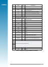
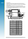
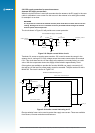
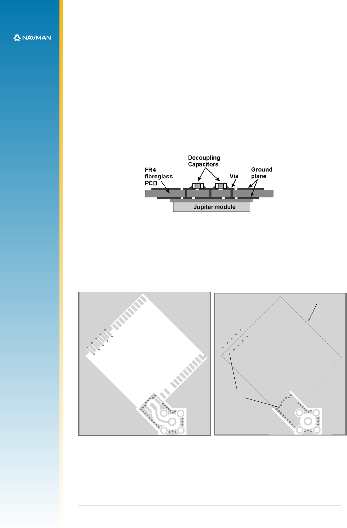
Decoupling components
The recommended values for power and signal decoupling are listed in Table 2-3. The
placement of these components must ensure that the low value capacitors have very
short tracks to the module pad, and very close vias connecting them to the ground plane.
(Figure 2-4 shows a typical layout).
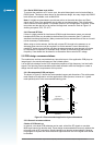
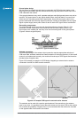
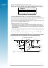
Figure 2-5: Example PCB layout for external active antenna
The modules can be used with a passive patch antenna if the connection to the antenna
input is very short. It is possible to mount the patch antenna on the same PCB as the module,
but to reduce the possibility of digital noise, it is recommended that the antenna be mounted
on the opposite side of the board to the module.
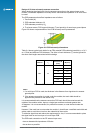
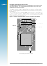
(Bottom)
(Top)
Through holes (vias)
Jupiter 30 / 20 outline
Figure 2-4: Typical module layout
Antenna connection
The PCB layout design of the antenna input connection requires appropriate selection of
PCB track width, substrate material and careful attention to the layout geometry. If this overall
system is not implemented correctly, the module will receive poor GPS signals and therefore
provide inferior navigation data.
Figure 2-5 illustrates an example of a PCB design integrating an external active antenna
connected via an MCX or SMA coaxial connector.