


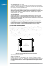

Antenna current limit using an IC
Jupiter GPS Module
16
17
18
19
20
21
22
23
24
25
26
27
28
29
30
GND
C5
100 nF
GND
GND
GND
GND
C4
100 nF
C6
18 pF
L2
120R / 100 MHz
OUT
ON
IN
FLAG
3
1
2
4
5
PWR_IN
antenna power enable
U3
MAX4785EXK–T
antenna short circuit sense signal
15
14
13
12
11
10
9
8
7
6
5
4
3
2
1
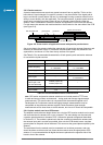
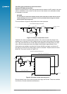
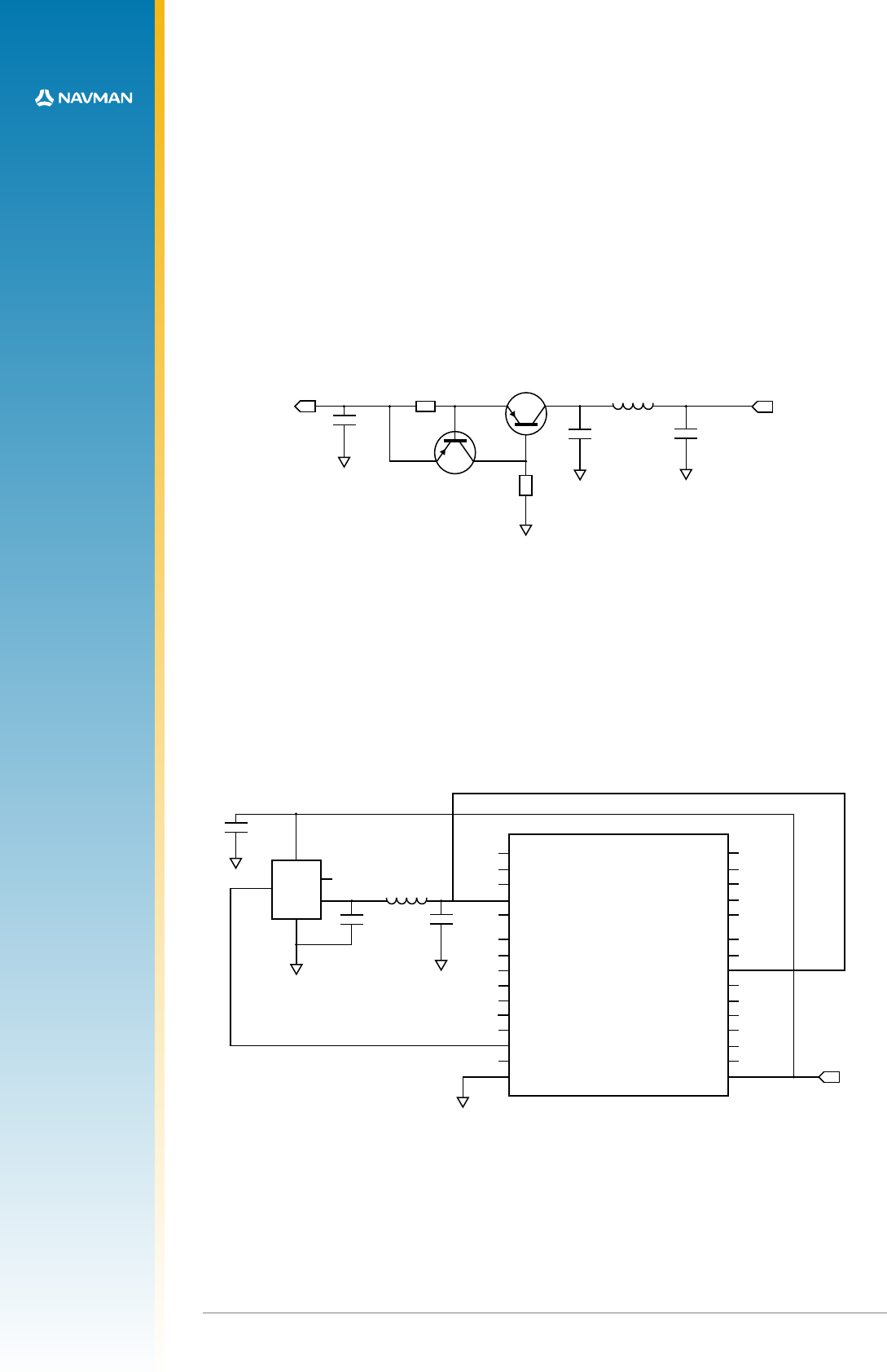
Figure 2-10: Active current limit using an IC
Electro-resistive fuses can be used to protect the supply over-current. These are available
from Bourns, Vitromon and other manufacturers.
LA000577C © 2006 Navman New Zealand. All rights reserved. Proprietary information and specications subject to change without notice.
14
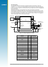
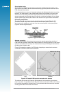
2.6.5 DC supply protection for an active antenna
Antenna DC supply current limit
When the Jupiter receiver is used with an external active antenna, the DC supply in the coax
cable is vulnerable to over-current if a fault occurs in the antenna or its cable gets crushed,
for example in a car door.
WARNING
It is important to note that the module antenna power feed does not have internal current
limiting. Damage can occur if unlimited current is permitted to ow through the module
antenna power feed components.
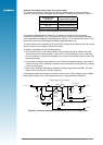
The circuit shown in Figure 2-9 will provide over-current protection.
70 mA Antenna supply current limit
R1
10R
C9
100nF
GND
SUPPLY_INPUT
3-5 VDC
200 mW
Q2
BC857B
Q1
BC857B
GND
GND GND
C8
100nF
C7
18pF
R10
1K
L3
120R / 100 MHz
ANTENNA_SUPPLY
(V_ANT)
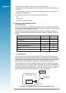
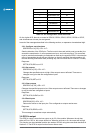
Figure 2-9: Simple current limiter circuit
Transistor Q1 serves as a series pass transistor. Q2 is used to sense the current in the
antenna circuit, turning off Q1 if the voltage across the current sense resistor R1 exceeds
0.6 V. This circuit does not turn off the supply to the antenna, but merely limits it to a safe
value. With the components shown the supply will be limited to approximately 70 mA.
Other options are available to provide this function. MAXIM can supply a current trip IC
that will turn off the load if a preset supply current is exceeded. The part number for this is
MAX4785. The circuit is shown in Figure 2-10.