


LA000577C © 2006 Navman New Zealand. All rights reserved. Proprietary information and specications subject to change without notice.
20
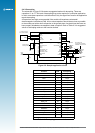
3.4 Navman proprietary NMEA low power mode messages
Navman has added a number of proprietary NMEA input messages to congure the
TricklePower and Push-To-Fix modes.
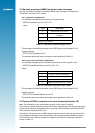
3.4.1 Low power conguration
The following message sets the receiver to low power mode:
$PSRF151,a,bbbb,cccc[*CS] <CR> <LF>
where:
Field Description
a Push-To-Fix* (1=on, 0=off)
b
TricklePower duty cycle (parts per
thousand)
c TricklePower on time (milliseconds)
*Note that Push-To-Fix
TM
does not require elds b and c
so they may be left blank
Table 3-1: Low power modes message values
This message is the NMEA equivalent of the SiRF Binary input message ID 151.
System response:
$PTTK,LPSET,a,bbbb,cccc*CS
The updated values returned by the system are as described in Table 3-1.
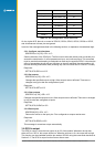
3.4.2 Low power acquisition conguration
The following message sets the acquisition parameters of the low power mode:
$PSRF167,aaaaaa,bbbbbb,cccc,d[*CS] <CR> <LF>
where:
Field Description
a maximum off time (milliseconds)
b maximum search time (milliseconds)
c Push-To-Fix period (seconds)
d adaptive TricklePower (1=on, 0=off)
Table 3-2: Low power acquisition input values
This message is the NMEA equivalent of the SiRF Binary input message ID 167.
System response:
$PTTK,LPACQ,aaaaaa,bbbbbb,cccc,d*CS
The updated values returned by the system are as described in Table 3-2.
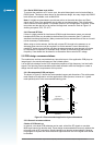
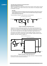
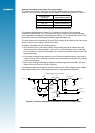
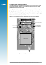
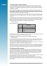
3.5 Control of GPIO connections via serial commands (Jupiter 20)
Note: The information in this section does not apply to the Jupiter 30 module.
The Jupiter 20 receiver has many unused GPIO (user programmable input output) signal pads.
These can be utilised in the application by introducing custom software written with the SiRF
SDK (Software Development Kit) tools.
Alternatively, the receiver has an NMEA default instruction protocol that can control these IO
ports through the standard serial communication ports using proprietary NMEA commands.
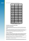
The GPIO lines are treated as a single 8-bit register, with the pins occupying the positions
shown in Table 3-3.