


LA000577C © 2006 Navman New Zealand. All rights reserved. Proprietary information and specications subject to change without notice.
12
• be interfaced to a coaxial connector if an external antenna is used
• have maximum clearance to ground on the same layer, or at least be half the substrate
thickness
• be routed away from noise sources such as: switching power supplies, digital signals,
oscillators and transmitters
The PCB track connection to the RF antenna input must NOT have:
• vias
• sharp bends
• components overlaying the track
2.6 Antenna system design choices
2.6.1 Antenna types
There are two major types of GPS antenna: passive and active. The active antenna has a
built in LNA (Low Noise Amplier) to increase the strength of the signal, and to compensate
for the signal loss in a long cable connection.
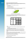
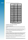
The features of each type of antenna are shown in Table 2-5, comparing an externally
mounted active antenna with a passive patch antenna mounted on the same PCB as the
module.
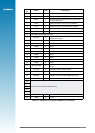
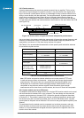
Feature Passive antenna Active antenna
requires short cable between antenna and receiver yes no
consumes power no yes
can be mounted remote from receiver no yes
gives good performance in poor signal situations no yes
has built in additional ltering no yes
low cost
yes no
requires a coaxial connector no yes
Table 2-5: Passive and active antenna features
2.6.2 Active antenna
An active antenna is a passive antenna with a built in LNA that requires a power supply.
Active antennas are used when the antenna input is connected to the receiver through a
coaxial cable (usually longer than 3 m) or any high loss transmission path. The GPS signals
experience loss in the transmission path from the antenna. The loss is overcome by the
antenna’s LNA, which amplies the signal before it enters the transmission path.
The amplication is also used to enhance the signal in areas of low signal. If the coaxial
cable is shorter than 3 m it may experience too much gain at the receiver and degrade the
performance. There are some variations as to how the antenna will receive its power but it
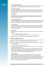
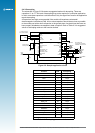
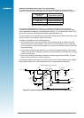
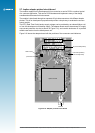
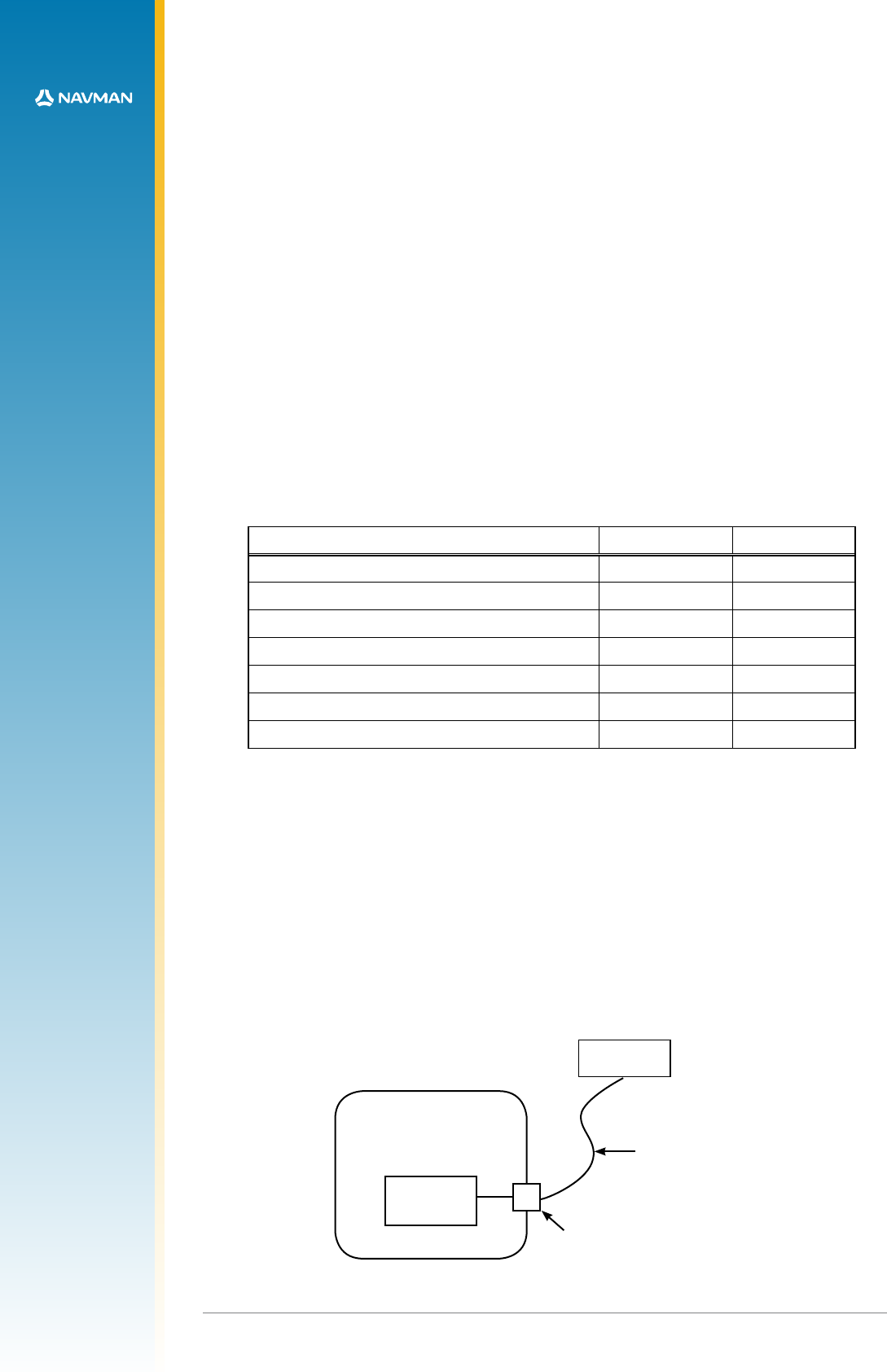
is usually supplied through the coaxial cable via the antenna input as shown in Figure 2-7.
(Refer to Table 2-6 for the recommended active antenna characteristics.)
Application PCB
Jupiter
module
Active GPS
antenna
connecting coax carrying
GPS signals and DC
power for amplication
coaxial connector
tted to application
PCB
Figure 2-7: Arrangement of active antenna and application board