


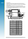
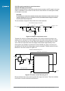
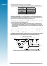

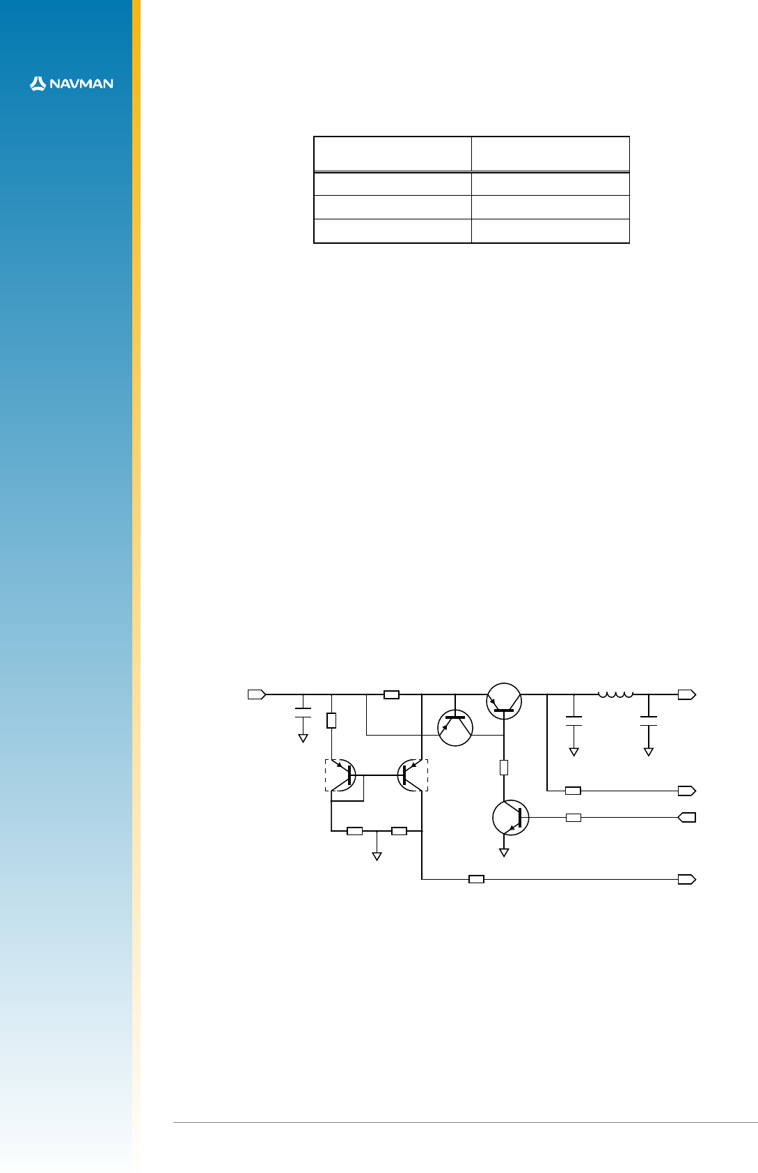
Figure 2-11: Antenna short/open circuit sensor circuit (3.3 V supply only)
V_ANT
L1
120R / 100 MHz
GND
GND
GND
C1
100 nF
C3
18 pF
R3
1K
GND
GND
SUPPLY_IN
C2
100 nF
Q4-A
BC857BS
R7
56R
R6
10R
200 mW
R5
5K6
R8
5K6
Q4-B
BC857BS
Q3
BC847B
R4
10K
R2
10K
R1
10K
Q1
BC857B
Q2
BC857B
NANT_SC
ANT_CTRL
ANT_OC
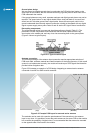
Discrete antenna current monitor
LA000577C © 2006 Navman New Zealand. All rights reserved. Proprietary information and specications subject to change without notice.
15
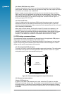
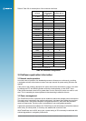
Antenna short/open sense inputs and control output
The Jupiter receiver has a digital input to provide signalling when an antenna fault has
occurred. These functions are shared with the Jupiter 30 GPIO pads as shown in Table 2-7.
Antenna sense
functions
Jupiter GPIO function
ANT_CTRL GPIO1 (ON=High)
ANT_OC GPIO15 (Active High)
NANT_SC GPIO3 (Active Low)
Table 2-7: Antenna sense and control functions
The reference design shown in gure 2-11 is indicative of an open-circuit switchover
threshold of approximately 3 mA. This maybe too high for some low-power antennae and
can be adjusted by changing the following resistor values – R7 to 12Ω and R3 to 2K2Ω. This
results in an open-circuit switchover threshold of approximately 2 mA.
The over current circuit consisting of Q1 and Q2 is the same as the simple current limit circuit
shown in Figure 2-9, providing a 70 mA current limit.
In addition, this design has the following features:
1. Q4-A and Q4-B form a low current sensor, thus providing a signal to indicate when the
antenna has become disconnected or open circuit. It is not mandatory to use a matched
pair of transistors, as shown in this design, but it will provide consistent results over a wide
temperature range.
2. Q3 provides a method for the receiver to turn off the active antenna supply in the event of
a fault occurring. This is a latched condition in the software and can be restored by issuing
a reset or power down.
3. Short circuit sensing is achieved by feeding the antenna supply into the NANT_SC input.
When a short circuit occurs, this line will go low.
This design provides the lowest cost solution for this function. Other designs can be created
giving higher stability over a wide temperature range, using operational ampliers.