


86
Appendix H
Unit Installation
The GPSMAP 182/182C/232 with external antenna can be fl ush mounted on a fl at panel of .08-
.52” thickness using the cam lobe feature on its gimbal mounting bracket. When fl ush mounting the
GPSMAP 182/182C/232, be sure to choose an appropriately sized location for the unit (see unit dimen-
sions pg. 83) and leave 1.25” (32mm) clearance below the data card slot for inserting/removing data
cards. For fl ush mounting the GPSMAP 232 unit, skip to the next set of instructions.
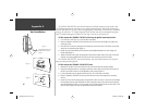
To fl ush mount the GPSMAP 182/182C unit using the gimbal mounting bracket:
1. Cut a 4.33”W x 4.33”H (110 x 110 mm) hole in the panel.
2. Place the GPSMAP 182/182C/232 into the hole from the front until the fl ange rests against the
mounting surface.
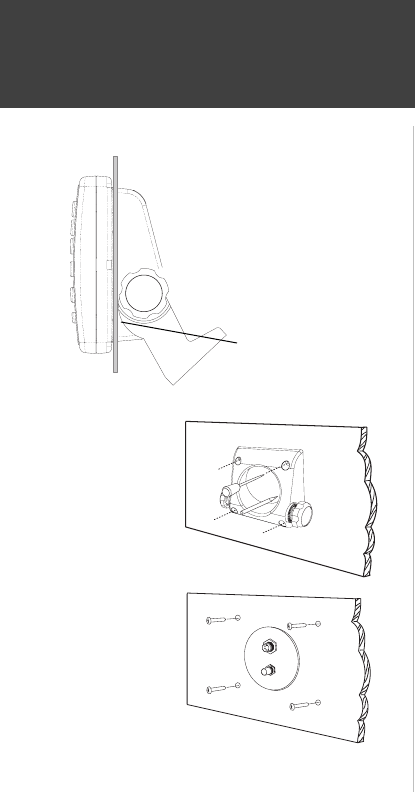
3. From the back of the panel, loosely attach the bracket such that the slot in the ratchet area points
away from the mounting panel (fi gure 1).
4. Rotate the bracket downward until the panel is pinched tightly between the unit’s fl ange and
bracket lobe (fi gure 1).
5. Tighten the knobs and connect the power/data and antenna cables. Note: if the panel is too thick
to allow use of the supplied knobs, two M6 screws may be used to secure the bracket.
The GPSMAP 182/182C/232, with external antenna, may also be fl ush mounted on a fl at panel
using its existing mounting bracket.
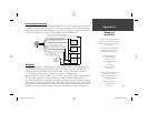
To fl ush mount the GPSMAP 182/182C/232 unit:
1. Remove the four M5 screws from the back of the unit and remove the mounting bracket.
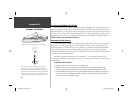
2. Using the mounting bracket as a template, outline the center relief area and mark the location of
the four screw holes centers on your bulkhead or other surface (fi gure 2).
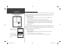
3. Cut the relief hole from the panel and drill the four 0.20” (5.08 mm) screw holes.
4. Place the GPSMAP 182/182C/232 into the relief hole until it rests fl ush against the mounting
surface.
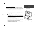
5. Secure the unit to the mounting surface using the M5 screws. Do not try to force the screws deeper
into the holes than the holes will allow. For thick mounting surfaces, insert the M5 screws directly
thru the drilled holes (fi gure 3). For thin panels, place the mounting bracket on the back side of the
panel for more support. Connect the power/data and antenna cables.
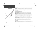
Figure 1
Figure 2
Figure 3
Pull gimbal bracket down
until cam lobe contacts
surface.
182C Manual Part 2.indd 86 6/4/2003, 2:54:32 PM