


98 GPSMAP 182/182C Owner’s Manual
APPENDIX > CONNECTING THE POWER/DATA CABLE
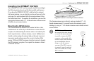
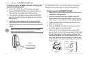
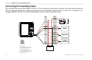
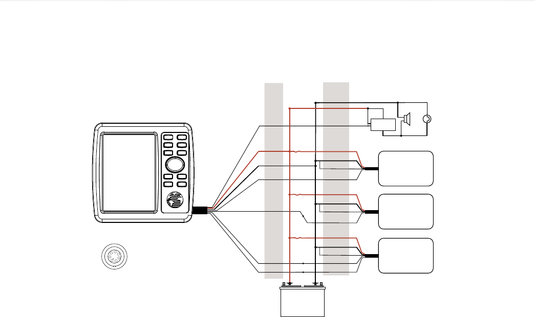
Connecting the Power/Data Cable
The power/data cable connects the GPSMAP 182/182C to a DC system and provides interface capabilities for connecting external devices.
The color code in the diagram below indicates the appropriate harness connections. Replacement fuse is a AGC/3AG - 2.0 Amp fuse. For
wiring the GPSMAP 182/182C to a GSD 20 Sonar Module, refer to the GSD 20 Installation Guide.
PIN 2 (black) Ground (Power and Data)
PIN 3 (blue) NMEA OUT (Com 1 TX)
PIN 4 (brown) NMEA IN (Com 1 RX)
PIN 5 (white) RTCM/NMEA IN (Com 2 RX)
PIN 6 (green) NMEA OUT (Com 2 TX)
PIN 7 (yellow) Alarm Low
PIN 1 (red) Power
PIN 2 (black) Ground (Power and Data)
PIN 3 (blue) NMEA OUT (Com 1 TX)
PIN 4 (brown) NMEA IN (Com 1 RX)
PIN 5 (white) RTCM/NMEA IN (Com 2 RX)
PIN 6 (green) NMEA OUT (Com 2 TX)
PIN 7 (yellow) Alarm Low
NMEA
Device with
Sonar Output
TXD +
Alarm Relay
100ma max
coil current
GSD 20,
Beacon
Receiver or
DSC VHF
Autopilot/
NMEA Device
DC
Power Source
RXD +
RXD -
RX+
TX+
100 ma
Max Coil Current