


1-6
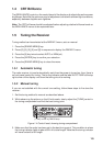
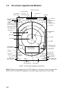
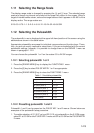
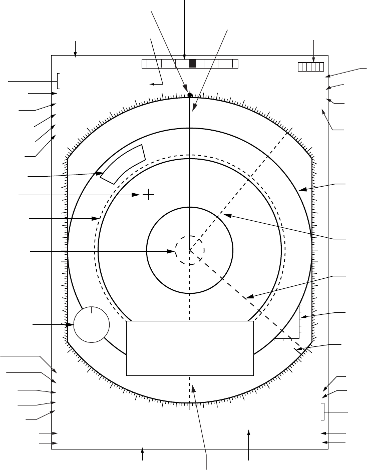
1.6 On-screen Legends and Markers
000
010
020
030
040
050
130
140
150
160
170
180
190
200
210
220
230
310
320
330
340
350
250
240
260
270
280
290
300
060
070
080
090
100
110
120
0° 30° 60° 90°30°60°90°
P
SB
WS
NE
10MIN
0
20
40
60
20-30
80
100
m
/MIN
DATA DISPLAY
(See next page.)
WATCH 5 : 30
ZOOM
X-BAND
A/C AUTO
NOISE REJ
OFFCENTER
EBL
044.4° T
>130.1° T<
INDEX
>236.8° T<
TRUE TRAIL
3MIN 1:25
TGT ALARM 1
TGT ALARM 2
VRM
>0.600SM<
0.150SM
0.75
/0.25SM
+0.350SM
330.0° T
HEAD UP RM
PULSE 1 M1
EAV3
IR1
ES3
2ND ECHO
HDG 123.4°T GYRO
SPEED 14.8KT WT LOG
ANT1 MAIN
SET & DRIFT
AUTO TUNE
Guard Alarm
Cursor
Wind data from
ext. equipment
No.1 VRM
No.2 VRM
Pulselength
Presentation
mode
Range and bearing
to cursor
Rate-of-Turn Scale
Zoom
No.1 VRM range
Range/Range
Ring Interval
Heading Line
X-band
A/C AUTO
No.2 EBL bearing
No.1 EBL bearing
Noise Rej.
Off-center
Echo Averaging
Interference Rej.
Echo Stretch
Target Trail
Trail Time/
Time Elapsed
Target Alarm
No.2 VRM range
Parallel Index
Lines Orientation
Stern Marker
Watch
Heading Marker
2nd Trace
Echo Rejector
North Marker
No.2 EBL
Fixed Range
Rings
Set & Drift
Antenna,
Display in use
Speed Source,
Speed
Heading
Tuning Bar
Depth data from
ext. equipment
No.1 EBL
Figure 1-5 On-screen legends and markers
Note: With the serial speed inputs and SOG selection, if the type of data is changed from
SOG to STW, the label SOG appears in red at the upper right corner on the screen.