


5-19
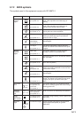
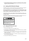
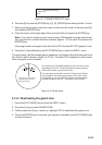
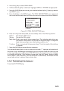
[GUARD ZONE SET]
1 [ARPA (1)]
2 1/2
Figure 5-11 GUARD ZONE SET menu
6. Press the [2] key and the [ENTER] key. ([2], [2], [ENTER] when setting the No. 2 zone.)
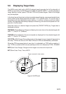
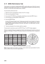
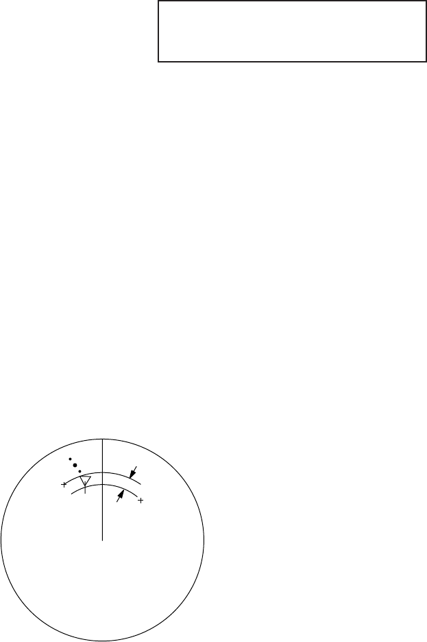
7. Referring to figure below, place the cursor at the outer left corner of the area (point A)
and press the [ENTER] key.
8. Place the cursor at the right edge of the area (point B) and press the [ENTER] key.
Note: If you wish to create a guard zone having a 360-degree coverage around own
ship, set point B in almost the same direction (approx. ±3°) as point A and press the
[ENTER] key.
If the range scale is changed to less than half of GZ, the label GZ OUT appears in red.
9. Press the [1] key followed by the [PLOT MENU] key to close the ARPA 1 menu.
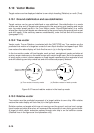
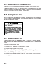
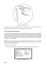
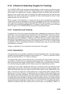
The guard zone, like the example below, appears on the display. Note that the guard zone
has a fixed radial extension (width) of 0.5 nm. The label GZ is displayed on the screen
when the guard zone is enabled.
Target in a guard zone is
marked by an inverted
flashing triangle.
A
B
0.5nm
No.1 guard zone is available between 3 and 6 nm with a fixed
range depth of 0.5 nm. The No.2 guard zone may be set any-
where when the No.1 guard zone is valid.
Two more alarm zones (No.1 and No.2 Target Alarm Zones)
may be added. This means a maximum of four alarm zones
are available at any time. ARPA symbols are not changed to
inverted triangles in the TAZ - only those in the GZ do so.
Figure 5-12 Guard zone
5.14.2 Deactivating the guard zone
1. Press the [PLOT MENU] key to show the ARPA 1 menu.
2. Press the [4] key to select GUARD ZONE.
3. Further press the [4] key to select (or highlight) OFF to deactivate the guard zone.
4. Press the [ENTER] key to conclude your selection followed by the [PLOT MENU] key
to close the menu.