


SP - 2
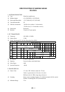
(4) Range Scales and Ring Intervals
0.125, 0.25, 0.5, 0.75, 1, 1.5, 2, 3, 4, 6, 8, 12, 16, 24, 32, 48, 96
0.025, 0.05, 0.1, 0.25, 0.2, 0.25, 0.5, 0.5, 1, 1, 2, 2, 4, 8, 8, 12, 12
(5) Range Accuracy 1% of range in use or 15 m whichever is the greater
(6) Range Discrimination 25 m
(7) Bearing Accuracy ±1°
(8) Bearing Discrimination 2.5°
(9) Presentation modes Head-up, Head-up TB, North-up, Course-up, True Motion North-up
(Heading signal required except for HU)
(10) Variable Range Markers Two Variable Range Markers, switched
(11) Offcenter Sweep origin can be offcentered by 50% of range in use in any direction
(Not available for maximum range)
(12) Guard Zone Anywhere above 0.7 SM
(13) Electronic Plotting Aids (EPA)
10 Targets Providing Range, Bearing, Course, Speed, CPA and TCPA
Note: EPA disabled when ARPA function is used.
(14) Parallel Index Lines 2, 3 and 6 lines (selectable on menu)
4. INTERFACE
(1) Gyrocompass Built-in interface accepts synchronized signal (20-50 V, 50-400 Hz)
(2) Speed Log Built-in interface accepts contact closure or DC signal at 200, 400 or 500
pulses/sm.
(3) External Radar (option) Built-in interswitch for 2 channels provided
5. POWER SUPPLY
(1) DC Source 24-32 VDC: 10.8-8.2 A, 260VA
(2) AC Source 100-115/220-230 VAC: 4.1 A, 1 phase, 50-60 Hz, 410 VA
6. ENVIRONMENTAL CONDITION
(1) Ambient Temperature (Complies with IEC60945)
Display Unit: -15°C to +40°C
Antenna Unit: -25°C to +70°C
(2) Relative Humidity 95% at 40°C
(3) Water proofing Display Unit (Panel): IPX2
Antenna Unit: IPX6
(4) Vibration ±1 mm ±10%, 2(5) to 13.2 Hz,
Maximum acceleration 7 m/s
2
, 13.2 to 100 Hz