


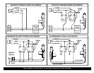


GREEN: (-) NEGATIVE LOCK Connect directly to negative lock/unlock systems. If vehicle uses
RED: +12V For Relays positive door lock signals or reversing polarity type, then external
BLUE: (-) NEGATIVE UNLOCK relays must be added. See Power Door Lock Wiring: Pages 8-
9.
4 PIN (WHITE) SENSOR PLUG:
WHITE: NEGATIVE PRE-WARN
BLACK: SENSOR GROUND
BLUE: NEGATIVE TRIGGER
RED: SENSOR POWER
3 PIN (BLUE) DATA PLUG ON RIGHT SIDE OF MODULE: Data port for 2-WAY FM Transceiver Box &
Antenna
4 PIN (WHITE) DATA PLUG ON RIGHT SIDE OF MODULE: Port for optional extended range antenna for 1-
way remote control.
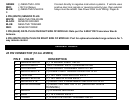
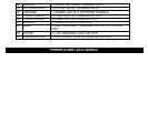
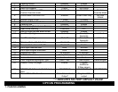
WIRING TABLE
20 PIN CONNECTOR (18 GA. WIRES)
PIN # COLOR DESCRIPTION
1 GREEN/WHITE (+) 12 BRAKE LIGHT INPUT
2 BLACK/GRAY TACH SIGNAL INPUT (ENGINE RPM0
3 WHITE/RED (-) AUXILIARY CHANNEL OUTPUT #2
4 BLACK/WHITE (-) DOME LIGHT SUPERVISION OUTPUT
5 YELLOW (+) 12V IGNITION SWITCH INPUT
6 BLUE/YELLOW (+) 12V GLOW PLUG INPUT
7 BLUE/WHITE (-) NEGATIVE PASSENGER UNLOCK OUTPUT
8 BLUE/ORANGE (-) NEGATIVE IGN. OUTPUT (GROUND WHEN
RUNNING)
9 BLACK (-) CHASSIS GROUND
10 RED (+) 12 POWER INPUT
11 VIOLET (+) POSITIVE DOOR TRIGGER INPUT