


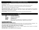


SUGGESTED COMPONENT MOUNTING
Control Module: Driver or Passenger side underdash, the unit should be placed as high as possible, not easily
accessible by an intruder.
Shock Sensor: Mount with wire ties to an under dash wire harness or fasten with screws to a panel.
Siren: Under the hood to fender-well or other body surface with the open end facing downward.
LED: In a visible location on the dashboard or console.
Override/Program button: Hidden location, but accessible to the user in case the system must be disarmed
without the use of the transmitter. This switch is also used to program certain features and to page/call the
transceiver from inside the vehicle if necessary.
Antenna Module: Inside front windshield (as high as possible) using supplied double sided tape.
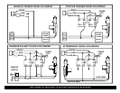
WIRING
6 PIN HI-CURRENT REMOTE START CONNECTOR:
RED: +12V INPUT (30 Amp Fused)
RED: +12V INPUT (30 Amp Fused)
YELLOW: IGNITION 1 (Primary) Output
ORANGE: ACCESSORY Output
PURPLE: STARTER Output
BROWN: Multi Function Output (IGNITION #2 / ACCESSORY #2 / STARTER #2)
(Programmable, See option table #23. Default set for IGN 2 output)
20 PIN MAIN HARNESS PLUG:
GREEN/WHITE WIRE: +12V BRAKE INPUT
Connect this wire to the side of the brake pedal switch that shows +12V only when the brake is depressed. This
input is used to reset remote start after entering the running vehicle and turning the ignition key on.
BLACK/GRAY WIRE: TACH SIGNAL INPUT (Used For Tach Mode)
Used to monitor Tach Pulses when the engine is running. Connect to negative terminal of ignition coil, crankshaft
position sensor or ECM/PCM tach wire.
WHITE/RED WIRE: (-) AUX. REMOTE OUTPUT #2 (Optional)