


B-5
Catalyst 6500 Series Supervisor Engine Guide
OL-7397-03
Appendix B Port, Cable, and Connector Specifications
Uplink Ports
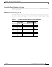
Console Port Mode 2 Signaling and Pinouts
This section provides the signaling and pinouts for the console port in mode 2 (CONSOLE PORT MODE
switch in the out position). See
Table B-4 for the pinouts.
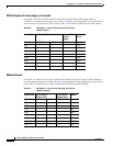
Uplink Ports
The Supervisor Engine 2, Supervisor Engine 32, Supervisor Engine 32 PISA, the Supervisor
Engine
720, Supervisor Engine 720-10GE, and the Supervisor Engine 2T all have Ethernet uplink ports
available on the front panel. These Ethernet ports can be used to provide additional port capacity for a
fully configured switch or can reduce the need to use a chassis slot for a Gigabit Ethernet module or
10-Gigabit Ethernet module where only a few Gigabit or 10-Gigabit Ethernet ports are required.
Table B-5 lists the supervisor engine model and the number and type of uplink ports available.
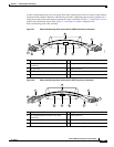
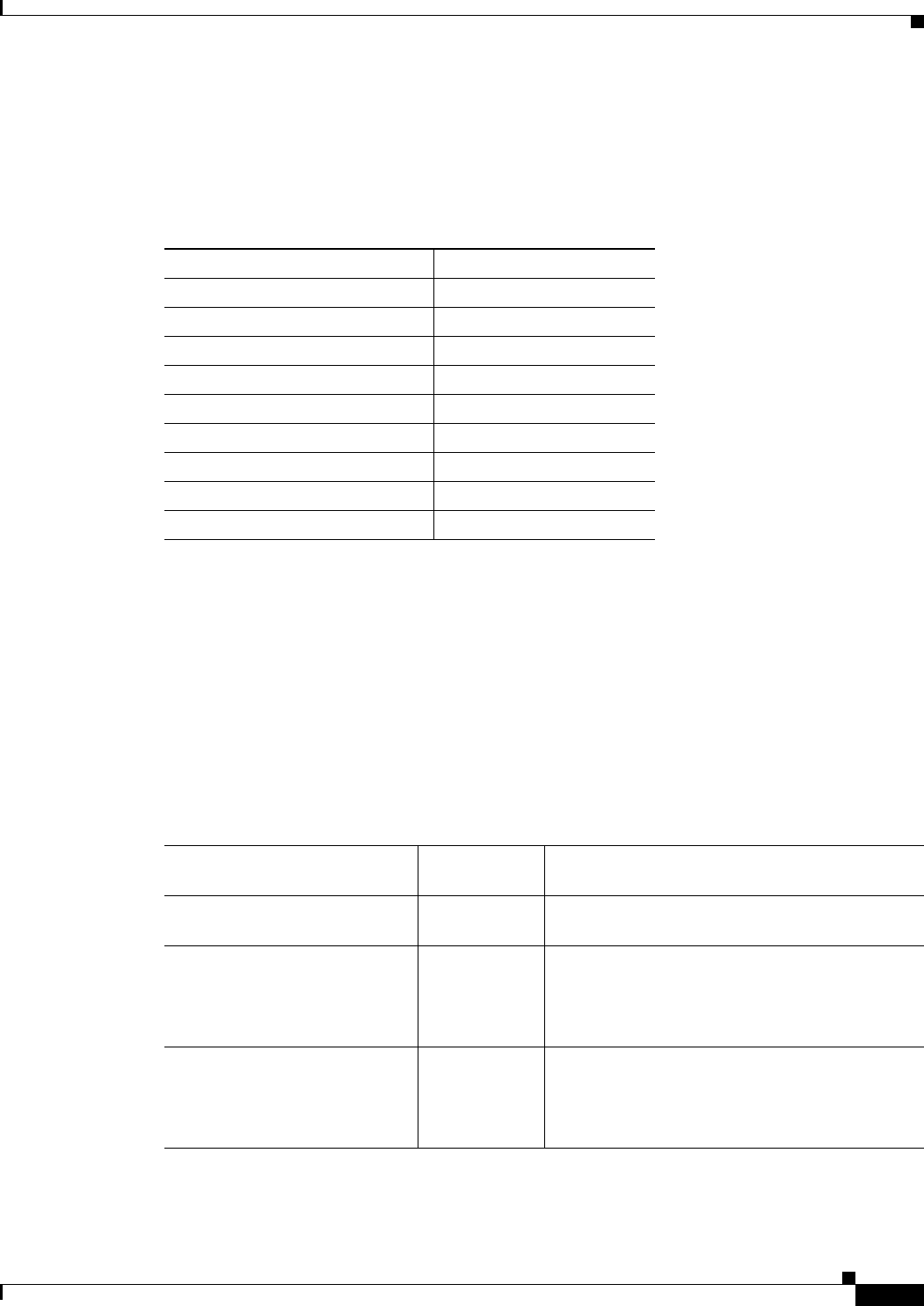
Table B-4 Console Port Pinouts (Port Mode Switch Out)
Console Port Console Device
Pin (signal) Input/Output
1 (RTS)
1
1. Pin 1 is connected internally to Pin 8.
Output
2 (DTR) Output
3 (RxD) Input
4 (GND) GND
5 (GND) GND
6 (TxD) Output
7 (DSR) Input
8 (CTS)
1
Input
Table B-5 Supervisor Engine Uplink Ports
Supervisor Engine Number of
Uplink Ports
Type of Uplink Port
Supervisor Engine 2 2 Two 1000BASE-X ports
(The two ports require GBIC transceivers.)
Supervisor Engine 32
(WS-SUP32-GE-3B and
WS-SUP32P-GE)
9 • Eight 1000BASE-X ports (The eight ports
require SFP transceivers.)
• One 10/100/1000 RJ-45 port (The port does
not require a pluggable transceiver.)
Supervisor Engine 32
(WS-SUP32-10GE-3B and
WS-SUP32P-10GE)
3 • Two 10-GBASE-X (The two ports require
XENPAK transceivers)
• One 10/100/1000 RJ-45 port (The port does
not require a pluggable transceiver)