


B-2
Catalyst 6500 Series Supervisor Engine Guide
OL-7397-03
Appendix B Port, Cable, and Connector Specifications
Console Port
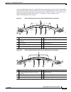
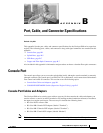
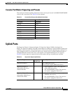
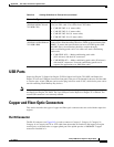
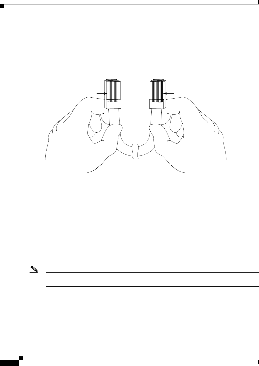
You can identify a rollover cable by comparing the two ends of the cable. Holding the cables
side-by-side, with the tab at the back, the wire connected to the pin on the outside of the left plug should
be the same color as the wire connected to the pin on the outside of the right plug. (See
Figure B-1.) If
your cable was purchased from Cisco Systems, pin 1 will be white on one connector, and pin 8 will be
white on the other (a rollover cable reverses pins 1 and 8, 2 and 7, 3 and 6, and 4 and 5).
Figure B-1 Identifying a Rollover Cable
CONSOLE PORT MODE Switch (Supervisor Engine 2 Only)
The supervisor engine front-panel CONSOLE PORT MODE switch, only on the Supervisor Engine 2,
allows you to connect a terminal or modem to the console port as follows:
• Mode 1—Switch in the in position. Use this mode to connect a terminal to the console port using
the RJ-45-to-RJ-45 rollover cable and DTE adapter (labeled “Terminal”).
You can also use this mode to connect a modem to the console port using the RJ-45-to-RJ-45
rollover cable and DCE adapter (labeled “Modem”).
• Mode 2—Switch in the out position. Use this mode to connect a terminal to the console port using
the Catalyst
5000 family Supervisor Engine III console cable and appropriate adapter for the
terminal connection (cable and adapter are not provided).
Note Use a ballpoint pen tip or other small, pointed object to access the CONSOLE PORT MODE switch. The
switch is shipped in the in position.
Pin 1
Pin 8
H3824
Pin 1 and pin 8
should be the
same color