


B-8
Catalyst 6500 Series Supervisor Engine Guide
OL-7397-03
Appendix B Port, Cable, and Connector Specifications
Copper and Fiber-Optic Connectors
Caution Category 5e, Category 6, and Category 6a cables can store high levels of static electricity because of the
dielectric properties of the materials used in their construction. Always ground the cables (especially in
new cable runs) to a suitable and safe earth ground before connecting them to the module.
Caution To comply with GR-1089 intrabuilding, lightning-immunity requirements, you must use foil-twisted pair
(FTP) cable that is properly grounded at both ends.
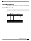
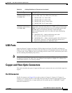
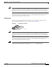
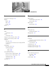
Figure B-2 RJ-45 Interface Cable Connector
Fiber-Optic Connectors
This section describes the SC and LC fiber-optic connectors used by the optical transceivers.
SC Connectors
Warning
Invisible laser radiation may be emitted from disconnected fibers or connectors. Do not stare into
beams or view directly with optical instruments.
Statement 1051
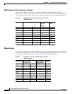
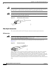
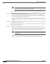
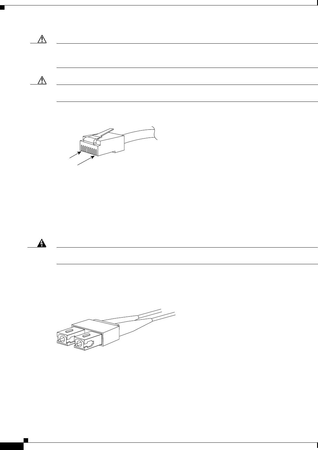
The SC connector is used to connect fiber-optic module ports with the external network. (See
Figure B-3.)
Figure B-3 SC Optical Connector
Always make sure that you insert the connector completely into the socket. This action is especially
important when you are making a connection between a module and a long distance (1.24 miles
[2
kilometers]) or a suspected highly attenuated network. If the link LED does not light, try removing
the network cable plug and reinserting it firmly into the module socket. It is possible that enough dirt or
skin oils have accumulated on the plug faceplate (around the optical-fiber openings) to generate
significant attenuation, reducing the optical power levels below threshold levels so that a link cannot be
made.
H1567
Pin 1
Pin 8
RJ-45 (both ends)
H2214