


3-10
Catalyst 6500 Series Supervisor Engine Guide
OL-7397-03
Chapter 3 Installing Supervisor Engines
Removing a Supervisor Engine
Removing a Supervisor Engine
This section describes how to remove a supervisor engine from the Catalyst 6500 series switch chassis.
Caution During this procedure, wear grounding wrist straps to avoid ESD damage to the module.
Warning
Invisible laser radiation may be emitted from disconnected fibers or connectors. Do not stare into
beams or view directly with optical instruments.
Statement 1051
Before you remove a supervisor engine, you should first upload the current configuration to a server.
This step saves time when bringing the module back online. You can recover the configuration by
downloading it from the server to the nonvolatile memory of the supervisor engine. For more
information, refer to Chapter 27, “Working with Configuration Files,” in the Catalyst
6500 Series Switch
Software Configuration Guide or in Chapter
4, Chapter 5, and Chapter 6 in the Catalyst 6500 Series
Cisco IOS Software Configuration Guide.
To remove a module from the chassis, follow these steps:
Step 1 Attach an ESD grounding strap to your wrist and to the ESD ground connector on the chassis or to a
properly grounded bare metal surface.
Note If you are unsure about the correct way to attach an ESD grounding strap, see the “Attaching
Your ESD Grounding Strap” section on page C-1 for instructions.
Step 2 Disconnect any network interface cables attached to the module.
Step 3 Verify that the captive installation screws on all of the modules in the chassis are tight.
Note This step ensures that the space created by the removed module is maintained. If the captive
installation screws are loose, the EMI gaskets on the installed modules will push the modules
toward the open slot, reducing the opening size and making it difficult to remove the module.
Step 4 Loosen the two captive screws on the module. Make sure that the two captive screws are completely
unscrewed from the chassis.
Step 5 Depending on the orientation of the slots in the chassis (horizontal or vertical), perform one of the
following two sets of steps:
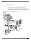
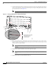
Horizontal slots
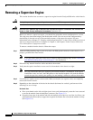
a. Place your thumbs on the left and right ejector levers and simultaneously rotate the levers outward
to unseat the module from the backplane connector. (See
Figure 3-5.)
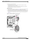
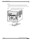
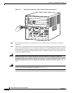
b. Grasp the front edge of the module and slide the module part of the way out of the slot. Place your
other hand under the module to support the weight of the module. Do not touch the module circuitry.
(See
Figure 3-6.)