


2-35
Catalyst 6500 Series Supervisor Engine Guide
OL-7397-03
Chapter 2 Supervisor Engines
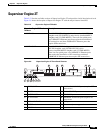
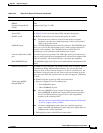
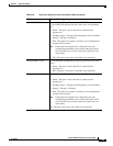
Supervisor Engine 2T
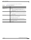
Memory
DRAM 2 GB
External CompactFlash
(disk0)
Compact flash Type 2 (1 GB)
Front panel features
Status LEDs See Table 2-24 for a list of the status LEDs and their descriptions.
RESET switch The RESET switch allows you to reset and restart the switch.
Note Because the reset switch is recessed in the supervisor engine
faceplate, you must use a ballpoint pen tip or other small, pointed
object to access the switch.
CONSOLE port This is a 10/100/1000 port that uses an RJ-45 connector. The CONSOLE port
allows you to access the switch either locally (with a console terminal) or
remotely (with a modem). The CONSOLE port is an EIA/TIA-232
asynchronous, serial connection with hardware flow control.
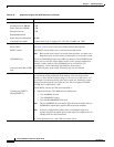
Universal Serial Bus (USB)
port
Two USB 2.0 ports are provided. The USB 5-pin mini Type-B connector is
used as a console port allowing attachment to PCs that are not equipped with
an RS-232 interface. The second USB port is currently not supported.
MANAGEMENT port A 10/100/1000 copper port used for out-of-band Ethernet management of the
switch.
DISK 0 slot and LED One PCMCIA slot is available. The PCMCIA slots allow a Flash PC card to
be installed providing additional flash memory. You can use this flash
memory to store and run software images or to serve as an I/O device. An
eject button is located on the left side, next to each slot. Pushing in on the
button ejects the Flash PC card from the slot. The slot supports 1
GB Flash
PC cards.
The PCMCIA slot has an activity LED associated with it.
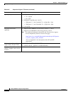
Uplink ports (PORT 1
through PORT
5)
• Supervisor Engine 2T has five uplink ports:
–
Two 10GBASE-X ports
–
Three 1000BASE-X ports
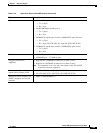
Note The two 10GBASE-X ports require X2 transceiver modules; the
three 1000BASE-X uplink ports require SFP transceiver modules.
For X2 and SFP transceiver support, refer to the compatibility
matrices at the following URL:
http://www.cisco.com/en/US/products/hw/modules/ps5455/produc
ts_device_support_tables_list.html
Note In chassis configurations where there are redundant supervisor
engines installed, the uplink ports on the supervisor engine that is in
standby mode are fully functional.
• Each uplink port has a link LED associated with it.
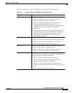
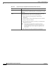
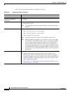
Table 2-22 Supervisor Engine 2T Features (continued)
Feature Description