


B-3
Catalyst 6500 Series Supervisor Engine Guide
OL-7397-03
Appendix B Port, Cable, and Connector Specifications
Console Port
Console Port Mode 1 Signaling and Pinouts
This section provides the signaling and pinouts for the console port in mode 1 (CONSOLE PORT MODE
switch in the in position).
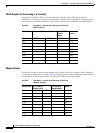
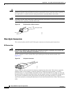
DB-9 Adapter (for Connecting to a PC)
Use the RJ-45-to-RJ-45 rollover cable and RJ-45-to-DB-9 female DTE adapter (labeled “Terminal”) to
connect the console port to a PC running terminal emulation software.
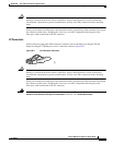
Table B-1 lists the pinouts for the
asynchronous serial console port, the RJ-45-to-RJ-45 rollover cable, and the RJ-45-to-DB-9 female DTE
adapter.
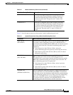
Table B-1 Port Mode 1: Console Port Signaling and Pinouts (DB-9 Adapter)
Console Port RJ-45-to-RJ-45
Rollover Cable
RJ-45-to-DB-9
Terminal Adapter
Console
Device
Signal RJ-45 Pin RJ-45 Pin DB-9 Pin Signal
RTS 1
1
1. Pin 1 is connected internally to Pin 8.
8 8 CTS
DTR 2 7 6 DSR
TxD 3 6 2 RxD
GND 4 5 5 GND
GND 5 4 5 GND
RxD 6 3 3 TxD
DSR 7 2 4 DTR
CTS 8
1
1 7 RTS