


3-22
Catalyst 6500 Series Supervisor Engine Guide
OL-7397-03
Chapter 3 Installing Supervisor Engines
Where to Go Next
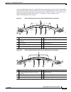
The mode-conditioning patch cord assembly is composed of duplex optical fibers, including a
single-mode-to-multimode offset launch fiber connected to the transmitter, and a second conventional
graded-index multimode optical fiber connected to the receiver. The use of a plug-to-plug patch cord
maximizes the power budget of multimode 1000BASE-LX/LH links.
Note The mode-conditioning patch cord is required to comply with IEEE standards. The IEEE found that link
distances could not be met with certain types of fiber-optic cable cores. The solution is to launch light
from the laser at a precise offset from the center, which is accomplished by using the mode-conditioning
patch cord. At the output end of the patch cord, the GBIC-LX/LH is compliant with the IEEE 802.3z
standard for 1000BASE-LX.
Connecting Transceivers to a Copper Network
Caution To comply with GR-1089 intrabuilding lightning immunity requirements, you must use grounded,
shielded, twisted-pair Category 5 cabling.
To connect transceivers to a copper network, follow these steps:
Step 1 Insert the network cable RJ-45 connector into the RJ-45 connector on the transceiver.
Note When connecting to a 1000BASE-T-compatible switch or repeater, use four-twisted-pair,
crossover Category 5 cabling.
Step 2 Insert the other end of the network cable into an RJ-45 connector on a 1000BASE-T-compatible target
device.
Where to Go Next
For complete information on verifying the installation of the supervisor engine configuration
information, see the Catalyst
6500 Series Switch Software Configuration Guide or the Catalyst 6500
Series Switch Cisco IOS Software Configuration Guide. For information on all Catalyst
6500 series
switch commands, see the Catalyst
6500 Series Switch Command Reference or the Catalyst 6500 Series
Switch Cisco IOS Command Reference publications.