


PAGE
1G-287 4/96
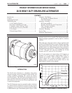
26-SI ALTERNATOR
E. NO OUTPUT
TEST EQUIPMENT NEEDED:
• Voltmeter
• Jumper Lead (18 ga. min; no fuse)
Note that 26-SI alternators must be connected to a
battery for the voltage sensing circuit to allow initial
turn on (refer to section on Features). When properly
connected and system checks indicate a “no output”
condition, use the following steps to determine if the
alternator requires repair:
! IMPORTANT
On alternators with insulated output terminal, voltage
in battery cable at output terminal cannot be checked
by touching voltmeter to connecting bolt. Disconnect
output terminal and check voltage at inner ring in
terminal connector of cable.
1. For alternators without an “I” terminal in use,
battery
positive voltage at the output terminal and residual
magnetism in rotor are necessary for alternator to turn
on. With engine stopped, use voltmeter to verify that
battery voltage is present in cable at output terminal. If
not, locate and correct cause of voltage loss.
Residual magnetism in the rotor is sometimes lost
during servicing of the alternator. The rotor can normally
be remagnetized without removing alternator from
application.
CAUTION: Do not allow jumper lead to be
accidentally grounded while connected to battery
insulated terminal. If the free end of this lead is
accidentally touched to the alternator housing or
other grounded areas, the jumper lead may quickly
get hot enough to cause a skin burn or to damage the
jumper lead. Keep jumper lead carefully insulated
from grounding during this procedure.
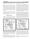
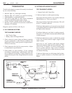
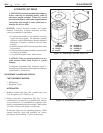
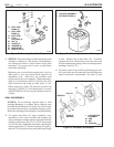
To remagnetize rotor, make sure the normal
connections are made to the alternator output terminal
and to the ground circuit. Disconnect the wiring harness
from the “R” terminal. Momentarily connect a jumper
lead from battery positive to the alternator “R” (or
unused “I”) terminal. (See Fig. 48) This will cause
field current to momentarily flow through the field
windings in the proper direction and restore magnetism.
Reconnect wiring harness to “R” terminal, then recheck
alternator for output.
2. For systems with an “I” terminal in use, the indicator
light current at this terminal will establish normal
magnetism at each engine start-up. Such systems may
depend on this current to help ensure a low turn-on
speed of the alternator. With engine stopped and key
switch in “run” position, use voltmeter to check for
voltage present at this terminal. With “I” terminal
connected and indicator lamp on, voltage will be less
than battery voltage. If necessary to disconnect wiring
at “I” terminal to make this check, check for battery
voltage in harness wire. If voltage is present, proceed
to Step 3. If no voltage is present, check “I” terminal
circuit for cause of voltage loss (bulb may be burned
out). Correct as necessary.
3. If no conditions have been found that might prevent the
alternator from turning on (Step 1 or 2), remove
alternator from engine in accordance with engine
manufacturer’s instructions and proceed to Unit Repair.
F. RATED OUTPUT CHECK
TEST EQUIPMENT NEEDED:
• Voltmeter
• Ammeter (current capability at least 15 amperes
higher than alternator rating)
• Variable Carbon Pile Load Test
CAUTION: Failure to disconnect grounded battery
cable at battery before removing or attaching battery
cable at alternator output terminal may result in an
injury. If a tool is shorted to the battery cable
connector at the output terminal, the tool can quickly
heat enough to cause a skin burn or the tool or cable
may be damaged.
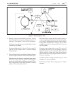
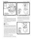
1. Refer to Fig. 9 for test equipment hookups as described
in following steps. If inductive pickup (“clamp on”)
type ammeter is used, place current clamp on alternator
output lead and skip to Step 4. If series ammeter is used,
disconnect grounded battery cable at battery first.
2. Install ammeter in series with alternator output terminal.
3. Reconnect grounded battery cable at battery.
4. NOTICE: When a 12-volt carbon pile load test is used
to diagnose a 24-volt system attach load test only to 12-
volt potential in battery pack. Attaching a 12-volt load
test to a 24-volt potential will damage the load test.
With load turned off, attach carbon pile load test across
battery.
5. Attach voltmeter lead to grounded battery terminal,
observing proper polarity for system. Leave other
voltmeter lead open for checks at various points.
6. Check and record voltage at insulated battery terminal.
For multi-battery systems, check voltage of battery set
connected as if in battery charging mode.
7. With all system electrical loads off, start engine and
run at moderate speed (rpm).
6