


26-SI ALTERNATOR
1G/287 4/96
PAGE
RECTIFIER DIODES
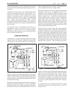
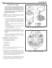
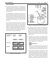
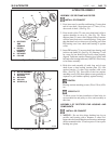
8. Disconnect the 6 diode leads from the 3 diode junction
studs by removing nuts. (See Fig. 17) Find the three
output side diodes (11), which are installed in the heat
sink (12). These diodes will be identical in polarity and
will commonly have the same color of insulation on the
diode lead wire.
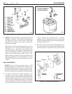
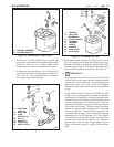
Use the ohmmeter or (for digital meters) the diode
check function of the multimeter to check the diodes.
Place one of the meter leads on a clean metal section of
the heat sink and connect the other lead to each of the
3 diode lead connectors, without allowing the connectors
to touch any other metal part. All 3 of these diodes
should read nearly the same, either all “open” or all low
resistance.
Reverse the leads and repeat these checks. All 3 diodes
should again read nearly the same, but should be
opposite from the first reading. If a diode reads the
same (either “open” or low resistance) in both checks,
replace it as described later in this section. If one diode
seems to have polarity opposite from the other two, or
if there is a question about whether the diodes are
installed properly for the polarity of the alternator,
refer to Fig. 18 for proper configuration.
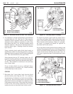
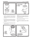
9. Find the three ground side diodes (10) mounted in the
rectifier end housing (1). (See Fig. 17) These diodes
will be identical in polarity and will commonly have
the same color of insulation on the diode lead wire.
Repeat the diode check described above (Step 8),
except use clean metal ground on the rectifier housing
instead of the heat sink. Refer to Fig. 18 to determine
proper polarity.
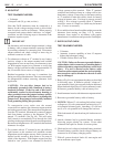
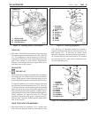
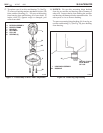
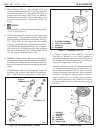
10. To replace one or more of the rectifier diodes,
disconnect all diode leads from the diode junction
studs (13). Remove three heat sink attachment screws
(31) and insulators (51), then remove the alternator
output terminal (16) by removing the inside nut,
washer, and insulator (17). (See Fig 19)
! IMPORTANT
Back of heat sink and both sides of heat sink
insulator are coated with silicone heat transfer grease.
If this grease is removed during testing, recoat as
described under regulator installation in this section.
Remove the heat sink and diode assembly (14) from
the rectifier end housing (1). (See Fig. 19) The
insulator (50) between the heat sink and housing may
come out with the heat sink. If it does, carefully peel
it from the heat sink. Check insulator for damage that
might result in a grounded condition and replace if
necessary. If insulator is to be reused, place it back
in the housing to prevent contamination of the grease.
11
Figure 19. Removing Heat Sink from Housing
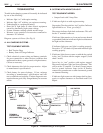
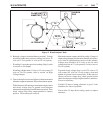
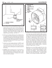
Figure 18. Diode Polarity
CURRENT
FLOW FROM
HOUSING TO
LEAD
BLACK WIRE
LEAD TO
HOUSING
RED WIRE
ALTERNATOR
GROUND
OUTPUT
DIODES
GROUND
DIODES
CURRENT
FLOW FROM
NEGATIVE LEAD TO
HEAT SINK
RED WIRES
HEAT SINK
IS LEAD
BLACK WIRE
POSITIVE
1. HOUSING
14. HEAT SINK
ASSEMBLY
13. STUD PACKAGE
16. TERMINAL
17. TERMINAL
31. SCREW
39. WASHER
50. INSULATION
51. INSULATOR
31
39
51
16
17
13
14
50
1
26-5026
26-5027