


PAGE
1G-287 4/96
26-SI ALTERNATOR
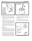
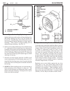
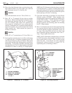
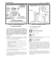
20. Place clip of red diode trio lead over hole in heat sink,
then install insulator (51), flat washer (39), and heat
sink attachment screw (31). (See Fig. 40)
TIGHTEN
Heat sink attachment screw to 3 N.m (26 lb. in.).
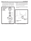
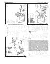
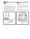
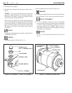
21. Place “R” or “I” terminal (18) into hole in rectifier
housing (1). Place insulating washer and plain washer
onto stud inside housing. (See Fig. 41) If alternator
uses “R” terminal, place yellow “R” terminal lead
from diode trio assembly (15) onto inside terminal
stud (18). If alternator has “I” terminal, install indicator
light lead assembly onto inside terminal stud. Install
inside terminal nut. Hold external hex portion of
terminal as anti-turn.
TIGHTEN
Inside “R” or “I” terminal nut to 2.3 N.m (20 lb. in.).
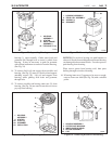
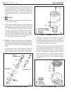
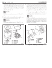
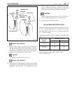
22. Coat regulator mounting area in rectifier end housing
(1) and both sides of regulator mounting plate (54)
with silicone dielectric grease (1974984). Place plate
into rectifier end housing, aligning holes with those in
the housing. If unit uses a regulator mounting plate
attachment screw (37) (1/2" long), install screw/washer
assembly (41) to hole A. (See Fig. 42) Finger tighten.
NOTE: On 25-SI alternators that have been converted
to 26-SI electronics, a spacer is installed between the
plate and housing at hole C prior to installing the plate.
Coat both ends of spacer with silicone dielectric grease
before placing over hole C in housing.
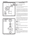
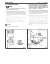
23. Coat back (metal side) of regulator (9) with silicone
dielectric grease (1974984). Place regulator onto
mounting plate, aligning mounting holes with those in
rectifier end housing. Install regulator grounding
attachment screw/washer assembly (35) (1" long)
through regulator and mounting plate into housing
hole D. Finger tighten.
24. Place “I” terminal lead (if used), blue lead from diode
trio, and long field coil lead over hole B (See Fig. 42)
and insert insulated regulator attachment screw (35)
(1" long). Place short field coil lead over hole C and
insert insulated regulator attachment screw (36) (1"
long). Finger tighten both screws.
NOTE: On 25-SI alternators that have been converted
to 26-SI electronics, the insulated attachment screw
that is used in hole C will be 2" long. A spacer is used
under the plate. Coat threads on screw with high
temperature adhesive/sealant (LoctiteC 272 or
equivalent) prior to installing in hole C.
20
Figure 41. Connecting "R" Terminal
Figure 42. Installing Regulator
1. HOUSING ASSEMBLY
15. DIODE TRIO ASSEMBLY
18. TERMINAL PACKAGE
"R" OR "I"
-or-
15
R-TERMINAL
18
1
TO "I" TERMINAL
TO DIODE TRIO
TO FIELD COIL
TO
FIELD
COIL
1. HOUSING ASSEMBLY
9. REGULATOR
35. SCREW (GROUND)
36. SCREW (INSUL.)
37. SCREW
41. WASHER
54. PLATE
36
35
36
41
54
37
9
A
C
D
1
26-5042
26-5043