


PAGE
1G-287 4/96
26-SI ALTERNATOR
- If voltage increases above 15 volts on 12-volt system
(or above 31 volts on 24-volt system), voltage is
uncontrolled. Turn carbon pile load off and stop test
stand. Recheck alternator for proper assembly. If
alternator has been assembled properly, replace regulator
as described under Unit Repair. Also check field coil
for shorts and replace if defective.
- If voltage is proper, proceed to next step.
4. With alternator running at highest rpm shown under
Cold Output in Specifications, turn on carbon pile load
and adjust to obtain maximum alternator output on
ammeter.
- If ammeter reading is within 15 amps of Cold Output in
Specifications, alternator is good. Turn off carbon pile
load and stop test stand.
- If ammeter reading is more than 15 amps below
specification, alternator is not operating properly. Turn
off carbon pile load and stop test stand. Return to Unit
Repair section in this manual and re-diagnose the
alternator.
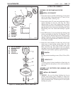
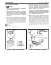
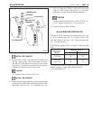
5. CAUTION: Do not allow jumper lead to be
accidentally grounded while connected to battery
insulated terminal. If the free end of this lead is
accidentally touched to the alternator housing or
other grounded areas, the jumper lead may quickly
get hot enough to cause a skin burn or to damage the
jumper lead. Keep jumper lead carefully insulated
from grounding during this procedure.
EQUIPMENT NEEDED:
• Jumper Lead (18 ga. min; no fuse)
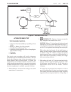
To restore residual magnetism in alternators with an
“R” or “I” terminal, alternator ground terminal must be
connected to battery ground terminal. This may be
done directly or through the test stand wiring. (See Fig.
48)
Disconnect carbon pile load test from battery if still
connected. Disconnect any leads connected to alternator
“R” or “I” terminal. Connect jumper lead under insulated
battery terminal. Without touching other grounded
areas (See CAUTION Above), momentarily touch
(“flash”) free end of jumper lead to alternator “R” or “I”
terminal. The momentary current flow into the terminal
will restore the proper magnetism in the rotor.
Disconnect the jumper lead from the battery, then
return to Step 1 and repeat Alternator Bench Test.
24
Figure 48. Restoring Residual Magnetism
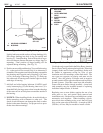
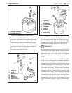
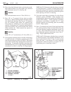
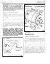
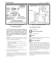
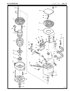
Figure 49. Installing Alternator on Engine
OUTPUT
TERMINAL
"R" or "I" TERMINAL
GROUND TERMINAL
ALTERNATOR
BATTERY
GROUND TERMINAL
ADJUSTMENT BRACKET
MOUNTING
NUT
ADJUSTMENT BOLT
FLAT WASHER
ALTERNATOR
ALTERNATOR
ADJUSTMENT
LUG
HINGE
BUSHING
MOUNTING
BRACKET
MOUNTING
BOLT
26-5047
26-5048