


26-SI ALTERNATOR
1G/287 4/96
PAGE
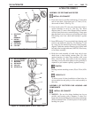
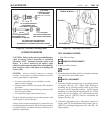
INSTALL OR CONNECT
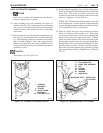
11. Ground lead, if used, to ground hole in rectifier end
housing, with ground screw/lockwasher assembly.
(See Fig. 53) If ground lead is not used, be sure screw/
lockwasher is installed in ground hole and properly
tightened to prevent entry of water or dirt.
TIGHTEN
1/4" ground screw to 6 N.m (55 lb. in.).
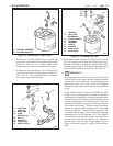
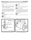
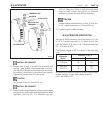
INSTALL OR CONNECT
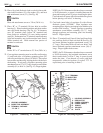
12. Battery cable to output terminal, using insulated output
terminal bolt or lock washer and output terminal nut as
applicable. (See Fig. 54) For insulated type, use
1971105 Chargelead Cable or equivalent and match
ridges in cable contact with grooves on alternator
terminal to provide anti-turn during installation.
TIGHTEN
Insulated output terminal bolt to 14 N.m (120 lb. in.),
or 1/4" output terminal nut to 7 N.m (65 lb. in.).
13. Connect negative cable at battery.
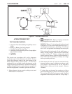
26-SI ALTERNATOR SPECIFICATION
The typical 26-SI Alternator rotor field check at 12-volts
is 3.0 - 4.3 current amps and 2.8 - 4.0 ohms @ 80
o
F. The
rotor field check at 24 volts is 2.0 - 2.8 current amps and
8.5 - 12.0 ohms at 80
o
F.
Cold Current output at 80
o
F is shown in the following
table.
1800 rpm 5000 rpm
12V/85A 56 85
24V/50A 33 50
24V/75A 45 75
For further information on rotations and exact specification
number on these or other Delco Remy Products:
Call 1-800-DRA-0222
27
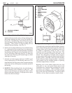
Figure 54. Connecting to Output Terminal
Alternator
Model
Amperes @ 80
o
F
TERMINAL NUT
WASHER
TO BATTERY
MALE OUTPUT
TERMINAL
ALTERNATOR
26-5053