


PAGE
1G-287 4/96
26-SI ALTERNATOR
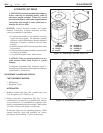
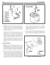
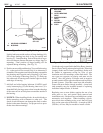
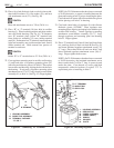
Lightly lubricate outside surface of hinge bushing (44).
Press hinge bushing into hole in lug on rectifier end
housing (1). Install bushing flush with inside of lug to
allow maximum distance between two hinge lugs for
mounting. Final position of hinge bushing will be
adjusted during mounting. (See Fig. 31)
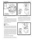
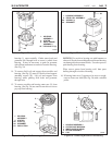
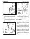
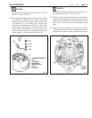
6. Position new rectifier end bearing (2) to rectifier housing
(1) so that seal will be toward rotor (4) as alternator is
assembled. Press against seal side of bearing to assemble
into housing until opposite end of bearing is 16.5 mm
(.65 in.) from edge of housing. (See Fig. 32) Push cap
into other end of housing until outside edges are flush
with edge of housing.
7. Add ball and roller bearing lubricant (1948791) until
cavity between plug (55) and bearing outer race (2) is
about half full, placing grease so that it touches the edge
of the outer race in several places around the outside of
the bearing.
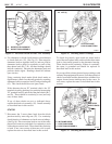
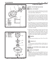
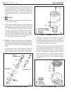
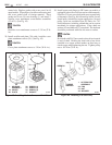
8. NOTICE: When installing diodes, do not hit diodes or
diode mountings with a hammer or other tool. The
shock of such an impact can damage the diode or other
diodes in the same mounting. Use proper tools to press
diodes into their mountings.
Use diodes only as specified in the Delco Remy America
Service Parts Catalog when replacing diodes. Heat sink
(output) diodes and in-frame (grounding) diodes will
be similar in appearance except for color of wire
insulation and color markings on the diode itself. The
two types are opposite in polarity and must not be
mixed. Also, the polarity of diodes used in negative
ground systems will be opposite of those used in positive
ground systems. Note that a new heat sink assembly
comes with new diodes already installed. A new heat
sink assembly may be installed instead of replacing
individual output diodes, if desired.
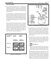
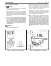
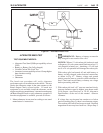
Replacing one or more diodes requires the use of an
arbor press or vise, and special diode removal and
installation tools. Such tools are available from various
automotive tool suppliers. When installing a diode,
press diode into mounting using a tool that will bear
only on the outer edge of the diode. As much as 890 N
(200 lbs.) of force may be needed to install a diode.
16
Figure 31. Installing Slip Bushing
Figure 32. Installing Rectifier End Bearing
INSTALL FLUSH
WITH INSIDE
OF LUG
1. HOUSING ASSEMBLY
44. BUSHING
1
44
1. RECTIFIER END
HOUSING
2. OUTER BEARING
RACE
3. INNER BEARING
RACE
4. ROTOR
ASSEMBLY
55. PLUG
2
3
4
2
55
1
26-5036
26-5038