


26-SI ALTERNATOR
1G/287 4/96
PAGE
be passed through this circuit to aid in alternator turn-on.
An “I” terminal is normally a threaded stud type with a 10-
24 thread.
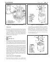
A threaded 1/4" hole (with screw and lockwasher) in the
rectifier end housing between the output and “R” or “I”
terminal is provided to connect a ground lead if used;
otherwise, the ground path is through the mounting
hardware and brackets to the engine. On replacement
units, a paper tag is present identifying the “ground
screw”; remove and discard the tag. The screw and
lockwasher should be installed in the housing regardless
of whether a ground lead is connected, to prevent entry of
dirt and water.
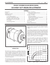
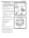
All electronic parts of the alternator are sealed in a
compartment to keep out moisture and dirt, and the
alternator is “inside cooled” by air drawn through a
baffled inlet in the rectifier end cover and exiting from the
drive end frame behind the fan.
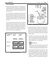
OPERATING PRINCIPLES
An alternator is a voltage-creating machine. The voltage
regulator limits the maximum voltage that the alternator
will produce at the output terminal by controlling the
magnetic field present in the stationary field. The output
voltage, induced in the stator and rectified by the diodes,
allows current to flow to satisfy the electrical loads placed
on the system, up to a maximum current that is characteristic
of the alternator design.
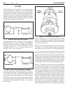
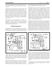
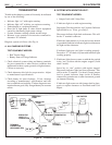
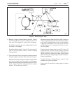
Schematics of the alternator circuitry are shown in Figure
6 (with “R” terminal) and Figure 7 (with “I” terminal).
With the alternator rotor turning, a magnetic field around
the stationary field coil is conducted by the rotor poles to
induce voltages in the stator windings. The faster the rotor
turns, the higher the induced voltage will be.
The initial voltages at start-up are generated by residual
magnetism in the rotor. On applications with an “I”
terminal in use, this magnetism will be boosted by a small
amount of current flowing through the field from the
indicator light circuit. As speed and output increase,
voltage available at the diode trio becomes sufficient to
supply field current for normal operation. When the
output voltage exceeds the battery voltage, the alternator
begins to drive the system voltage. If the wiring system
includes an indicator light, the presence of system voltage
at the diode trio equalizes the voltage on both sides of the
indicator light and the light goes out.
While the system voltage is below the voltage regulator
setting, the regulator turns on the field current and allows
the alternator to produce as much output as possible for the
alternator speed (rpm), temperature and system voltage.
When the voltage setting is reached, the regulator turns the
field current off. When the field current is turned off, the
magnetic field in the rotor collapses and the alternator
output voltage begins to fall. The falling voltage causes
the regulator to turn the field current back on and the
magnetic field to rebuild. This switching action of the
regulator continues rapidly, keeping the output and system
voltage very close to the voltage setting. This will continue
unless the electrical demands of the system cause the
system voltage to fall below the voltage setting. Should
this happen, the regulator will again allow full field
current to flow so that the maximum output of the alternator
at the given speed, temperature and system voltage is
realized.
An internal sense lead installed between the output
terminal/diode heat sink and regulator stud, is used for
voltage control.
Figure 6. Alternator Schematic with R Terminal
Figure 7. Alternator Schematic with I Terminal
3
REGULATOR
CAPACITOR
DIODE TRIO
ROTOR
STATOR
RECTIFIER BRIDGE
B-
B+
R
26-5014
REGULATOR
CAPACITOR
DIODE TRIO
ROTOR
STATOR
RECTIFIER BRIDGE
GROUND
B-
B+
I
26-5015