


PAGE
1G-287 4/96
26-SI ALTERNATOR
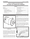
FEATURES
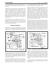
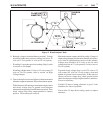
The 26-SI alternator is designed for a “one-wire” charging
system configuration. “One-wire” refers to the minimum
number of lead wire connections necessary at the alternator
for operation and requires only that the alternator output
terminal be connected to the battery insulated (positive for
a negative-ground system) terminal and that a ground
path be provided between the alternator housing and the
battery ground terminal. (See Figure 3)
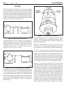
Some applications use an “I” terminal circuit to power an
indicator light and/or to lower the engine speed (RPM) at
which the alternator will turn on. Typical system wiring
using this type of circuit is shown in Figure 4. This is
commonly referred to as a “one-wire system with I
terminal” or as a “two-wire system.”
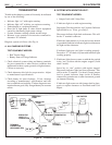
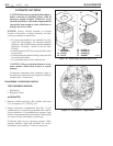
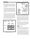
External connections to the 26-SI alternator are made to
terminals shown in Figure 5. The standard output terminal
is a “female” type with insulated connecting bolt and
charge lead cable with a special connector. When installed,
the electrical connection is sealed from moisture and there
are no exposed parts with battery voltage. The connector
bolt head is normally stamped “No Volts” to indicate the
insulated type.
Figure 5. 26-SI Electrical Terminals
Figure 3. Basic One-Wire System
Figure 4. One-Wire System with I Terminal
2
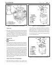
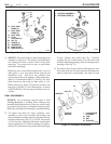
Some 26-SI models use a 1/4" threaded stud type of output
terminal. With this type of terminal, the exposed metal
parts are not insulated and will have battery voltage when
connected to the battery.
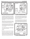
Optional connections to the 26-SI series include either an
“R” (relay) or “I” (indicator light) terminal, and a ground
lead connection to the alternator’s rectifier end housing.
An “R” or relay terminal is located on the side of the
alternator opposite from the output terminal. This terminal
may be used to operate some types of charge indicators, an
ADLO system, a tachometer, or similar device by providing
voltage pulses at a frequency of 8 pulses for each revolution
of the alternator. The current draw of the accessories being
powered through this terminal must not exceed 4 amperes.
“R” terminals are normally of the unthreaded pin type.
When an “I” terminal is present it will be located on the
side of the alternator opposite from the output terminal, in
place of the “R” terminal. An “I” terminal is connected
internally to the field circuit. An indicator light connected
in series with this terminal will glow whenever there is a
voltage difference between the “positive” side of the field
circuit and the system voltage at other side of the indicator
light. During normal alternator operation, the light will be
off since the diode trio output voltage equals the system
voltage. A side benefit of this circuit is that current is
passed through the field winding during engine start-up,
resulting in a lower alternator turn-on speed. A diode or
resistor may be used instead of a light bulb if no indicator
light is needed. (See Fig. 4) Up to 1 ampere of current may
A
V
GENERATOR
BATTERY
GENERATOR
BATTERY
GROUND
OUTPUT
TERMINAL
(B+)
"R" or "I"
TERMINAL
26-5011
26-5012
26-5013