


26-SI ALTERNATOR
1G/287 4/96
PAGE
FINAL ALTERNATOR ASSEMBLY
15. CLEAN
Inner race of rectifier end bearing (on rotor shaft) to
prevent contamination of grease.
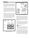
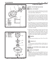
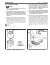
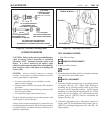
16. Align mounting lugs and assemble two halves of
alternator (See Fig. 39), inserting rectifier end bearing
inner race (on rotor shaft) into rectifier end bearing in
rectifier housing. Do not fully seat drive end housing
at this time.
17. Insert 4 thru-bolts (43) through drive end housing (6)
and stator (5) into threaded holes in rectifier housing
(1). Align housings and stator as needed to allow thru-
bolts to stand straight in holes and engage threads.
When all four thru-bolts are inserted, tighten them in
round-robin fashion to fully seat both housings against
shoulder on stator.
TIGHTEN
Thru-bolts to 6.2 N.m (55 lb. in.)
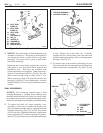
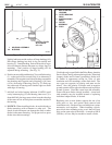
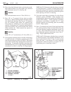
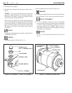
18. Install diode trio assembly (15) to rectifier end housing.
(See Fig. 40) Install diode trio and capacitor attachment
screw (38). This screw provides a ground for the
capacitor in the diode trio assembly and must hold tab
securely. Tighten to 3 N.m (26 lb. in.).
NOTE: On 25-SI alternators that have been converted
to 26-SI electronics, coat the threads of the attachment
screw with high temperature adhesive/sealant (LoctiteC
272 or equivalent) prior to installation.
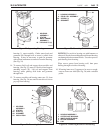
19. Place two diode lead clips onto each diode junction
stud (13) in the heat sink assembly (14). Next, place
one stator lead onto each of these studs, matching the
length of the leads to the appropriate studs. Finally,
place one yellow diode trio lead onto each stud, again
matching the length of the lead to the appropriate stud.
Install a diode trio to stator lead attaching nut (25) onto
each diode junction stud. Position clips under nuts so
that leads are routed without being pinched or pulled
tight against sharp surfaces. Tighten nuts to 3 N.m 26
(lb. in.).
19
Figure 39. Assembly of Alternator Halves Figure 40. Installing Diode Trio Assembly
14. HEAT SINK ASSEMBLY
13. STUD PACKAGE
15. DIODE TRIO ASSEMBLY
25. NUT
38. SCREW
39. WASHER
40. WASHER
51. INSULATOR
MOUNTING HOLE
DIODE LEAD
(6 PLACES)
38
40
15
25
14
39
31
51
13
26-5041
1. HOUSING
ASSEMBLY
5. STATOR
6. DRIVE FRAME
ASSEMBLY
43. THRU-BOLTS (4)
1
5
6
43
26-5031