


PAGE
1G-287 4/96
26-SI ALTERNATOR
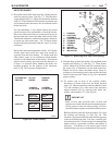
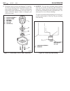
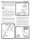
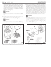
11. Place insulator (17b) on output terminal (17a) and
install through hole in housing (1). (See Fig. 36) Install
flat insulator washer (17c), aligning flat shoulders on
terminal with slot in heat sink to fully seat terminal.
Install nut/washer assembly (17d) onto threaded portion
of terminal inside housing. Tighten nut to 5 N.m (45
lb. in.).
12.
TIGHTEN
Two previously installed heat sink mounting screws
(31) to 3 N.m (26 lb. in.).
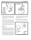
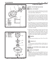
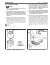
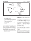
13. Lubricate grommet (49) on field coil leads lightly with
petroleum jelly. Turn grommet and leads so that leads
will be properly positioned after installation. (See Fig.
37) Place field coil and support (8) into rectifier
housing (1), guiding leads through hole into electronics
compartment and aligning mounting holes in support
with screw holes in rectifier housing. Push grommet
into hole in housing until fully seated. Install 3 field
coil and support attachment screws (29).
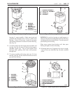
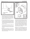
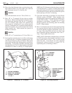
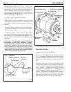
14. NOTICE: Handle stator with care to avoid bending
windings or breaking varnish insulation on windings.
If windings are damaged before or during installation,
they may become shorted and cause reduced alternator
output.
Straighten stator leads to ease installation. Lubricate
grommet (48) on stator leads lightly with petroleum
jelly. Welded junction connector on stator must be
positioned straight up from windings to prevent
grounding to housing or rotor when alternator is
assembled. Straighten stator lead wires all the way to
the windings and insert through hole in housing into
electronics compartment. (See Fig. 38)
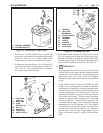
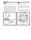
Align thru-bolt holes in stator (5) with those in housing
(1). Push stator into housing far enough to hold it in
place, being sure grommet (48) on wires is inserted
into hole in housing at the same time. Stator lead wires
should be stiff enough to push grommet into hole as
stator is installed (if not, carefully push on grommet
with a blunt instrument to seat it in the hole). It is not
necessary for the stator to be fully seated in housing at
this time.
18
Figure 36. Installing Output Terminal
Figure 37. Installing Field Coil
Figure 38. Installing Stator
OUTPUT
TERMINAL (16)
17a
17b
17c
17d
HOUSING (1)
HEAT
SINK (14)
OPTIONAL (17)
1. HOUSING ASSEMBLY
8. FIELD COIL ASSEMBLY
6. SCREW (3)
49. GROMMET
29
1
8
49
1. HOUSING
ASSEMBLY
5. STATOR
46. CLIPS (3)
48. GROMMET
52. INSULATION
5
48
52
46
1
26-5040
26-5033
26-5032