


PAGE
1G-287 4/96
26-SI ALTERNATOR
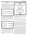
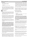
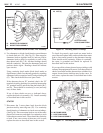
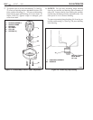
6. Use ohmmeter or diode check function on multimeter
to check diode trio (15). (See Fig. 15) Place negative
ohmmeter lead on regulator lead (A) and use positive
ohmmeter lead to check for continuity to each of the
three phase leads (B, C, D). All three readings should
indicate continuity. Reverse the ohmmeter leads and
perform checks again. Readings should all indicate
open circuits.
Using continuity check mode (diode check mode on
digital meter), check for a shorted capacitor by touching
ohmmeter leads to capacitor lead (F) and grounding tab
(G). This check should show an open circuit.
If the alternator has an “R” terminal, check the “R”
terminal circuit by checking for continuity between the
“R” terminal lead (E) and each of the phase leads (B, C,
and D). There should be continuity to one (and only
one) of these leads.
If any of these checks are not as indicated above,
replace the diode trio assembly (15). Install assembly
as described later in this section.
STATOR
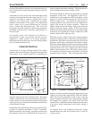
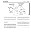
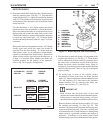
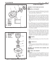
7. Disconnect the 3 stator phase leads from the diode
junction studs by removing nuts (25). Use continuity
check function of ohmmeter to check stator windings.
(See Fig.16) Place one meter lead on one of the stator
phase lead connectors and check for continuity to each
of the other two stator leads. There should be continuity
to both. If not, one or more of the stator coils is open;
replace the stator as described later in this section.
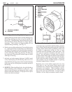
To check for grounds, again touch one meter lead to
one of the stator phase leads, and touch the other meter
lead to clean metal ground on the alternator housing.
There should not be continuity. If there is continuity,
the stator is grounded and should be replaced as
described later in this section.
It is not possible to detect shorted stator windings with
ordinary shop equipment. However, if all other electrical
checks are normal and the alternator has exhibited low
output, shorted stator windings may be the cause. In
such cases, replace the stator as described later in this
section.
10
Figure 15. Electrical Check of Diode Trio Assembly
Figure 16. Checking Stator Windings
OHMMETER
13. DIODE STUD PACKAGE
15. DIODE TRIO ASSEMBLY
A
E
G
D
C
F
B
15
13
25. NUT (3)
STATOR PHASE
LEAD CONNECTION
OHMMETER
25
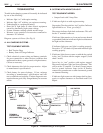
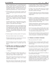
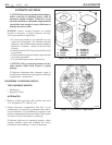
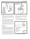
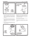
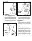
Figure 17. Checking Rectifier Diodes
OHMMETER
RECTIFIER
DIODE LEADS
OHMMETER
10. IN FRAME DIODE
11. HEAT SINK DIODE
14. HEAT SINK ASSEMBLY
10
11
14
10
26-5023 26-5024
26-5025