


8 - 35
– +
ELEC
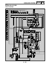
SIGNALING SYSTEM
EAS00797
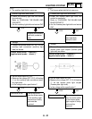
2. The tail/brake light fails to come on.
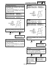
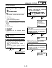
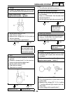
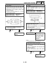
2. Voltage
• Connect the pocket tester (DC 20 V) to the
horn connector at the horn terminal as shown.
Positive tester probe
→
pink
1
Negative tester probe
→
ground
• Set the main switch to “ON”.
• Push the horn switch.
• Measure the voltage (DC 12 V) of pink at
the horn terminal.
• Is the voltage within specification?
YES
NO
The wiring circuit from
the main switch to the
horn connector is faulty
and must be repaired.
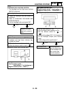
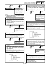
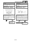
3. Horn
• Disconnect the black connector at the horn
terminal.
• Connect a jumper lead
1
to the horn ter-
minal and ground the jumper lead.
• Set the main switch to “ON”.
• Push the horn switch.
• Does the horn sound?
NO
YES
Replace the horn. The horn is OK.
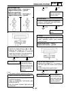
1. Tail/brake light bulb and socket
• Check the tail/brake light bulb and socket
for continuity.
Refer to “CHECKING THE BULBS AND
BULB SOCKETS”
• Are the tail/brake light bulb and socket OK?
YES
NO
Replace the tail/
brake light bulb,
socket or both.
2. Brake light switches
• Check the brake light switches for continuity.
Refer to “CHECKING THE SWITCHES”.
• Is the brake light switch OK?
YES
NO
Replace the brake
light switch.
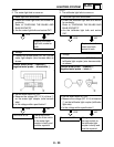
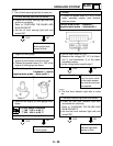
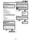
3. Voltage
• Connect the pocket tester (DC 20 V) to the
tail/brake light coupler (wire harness side)
as shown.
Positive tester probe
→
yellow
1
Negative tester probe
→
black
2
• Set the main switch to “ON”.
• Pull in the brake lever or push down on the
brake pedal.
• Measure the voltage (DC 12 V) of yellow
1
on the tail/brake light coupler (wire har-
ness side).
• Is the voltage within specification?