


1 - 2
GEN
INFO
FEATURES
FEATURES
OUTLINE OF FI SYSTEM
The main function of a fuel supply system is to provide fuel to the combustion chamber at the opti-
mum air-fuel ratio in accordance with the engine operating conditions and the atmospheric tempera-
ture.
In the conventional carburetor system, the air-fuel ratio of the mixture that is supplied to the com-
bustion chamber is created by the volume of the intake air and the fuel that is metered by the jet that
is used in the respective chamber.
Despite the same volume of intake air, the fuel volume requirement varies by the engine operating
conditions, such as acceleration, deceleration, or operating under a heavy load. Carburetors that
meter the fuel through the use of jets have been provided with various auxiliary devices, so that an
optimum air-fuel ratio can be achieved to accommodate the constant changes in the operating con-
ditions of the engine.
As the requirements for the engine to deliver more performance and cleaner exhaust gases
increase, it becomes necessary to control the air-fuel ratio in a more precise and finely tuned man-
ner. To accommodate this need, this model has adopted an electronically controlled fuel injection
(FI) system, in place of the conventional carburetor system. This system can achieve an optimum
air-fuel ratio required by the engine at all times by using a microprocessor that regulates the fuel
injection volume according to the engine operating conditions detected by various sensors.
The adoption of the FI system has resulted in a highly precise fuel supply, improved engine
response, better fuel economy, and reduced exhaust emissions. Furthermore, the air induction sys-
tem (AI system) has been placed under computer control together with the FI system in order to
realize cleaner exhaust gases.
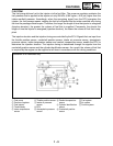
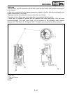
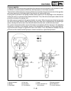
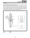
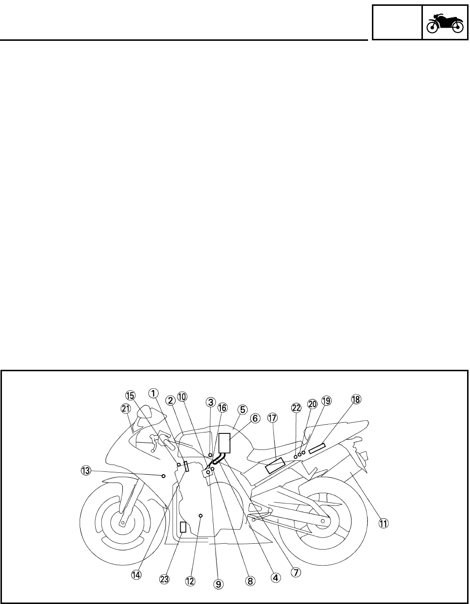
1
Ignition coil
2
Air filter case
3
Intake temperature
sensor
4
Fuel delivery hose
5
Fuel tank
6
Fuel pump
7
Fuel return hose
8
Intake air pressure
sensor
9
Throttle position sensor
0
Fuel injector
A
Catalytic converter
B
Crankshaft position
sensor
C
Coolant temperature
sensor
D
Spark plug
E
Cylinder identification
sensor
F
Pressure regulator
G
Battery
H
ECU
I
Atmospheric pressure
sensor
J
Fuel injection system
relay
K
Engine trouble warn-
ing light
L
Lean angle cut-off
switch
M
Air cut-off valve