


7 - 9
FI
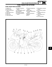
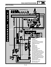
FUEL INJECTION SYSTEM
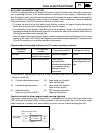
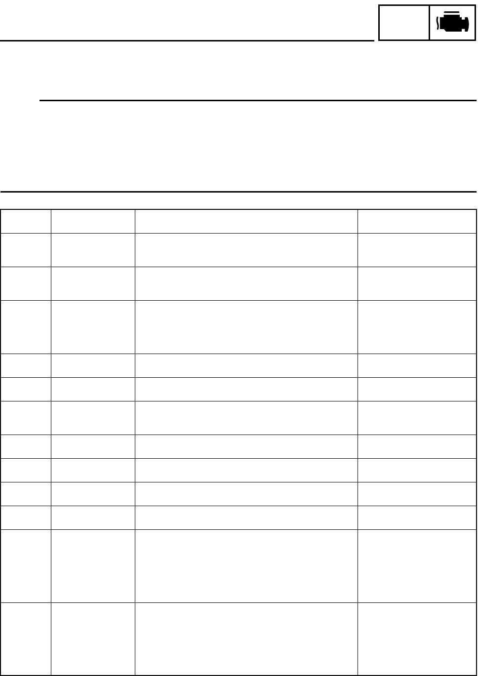
Diagnostic mode table
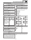
Set the meter display from the regular mode to the diagnosis mode. For the setting method, refer to
“DIAGNOSTIC MODE”.
NOTE:
• Check the intake temperature and coolant temperature as close as possible to the area in which
the respective sensor is mounted.
• If it is not possible to check it with an atmospheric pressure gauge, judge it by using 760 mmHg
(29.9 inHg) as the standard.
• If it is not possible to check the intake temperature, use the ambient temperature as reference
(use the compared values for reference).
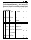
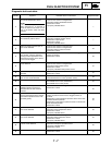
Diagnostic
code
Item Description of action
Data displayed on meter
(reference value)
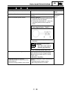
01
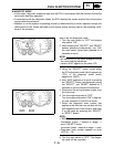
Throttle angle Displays the throttle angle.
• Check with throttle fully closed.
• Check with throttle fully open.
0 ~ 125 degrees
• Fully closed position (15 ~ 17)
• Fully open position (97 ~ 100)
02
Atmospheric pres-
sure
Displays the atmospheric pressure.
* Use an atmospheric pressure gauge to check the atmo-
spheric pressure.
Compare it to the value dis-
played on the meter.
03
Pressure difference
(atmospheric pres-
sure - intake air pres-
sure)
Displays the pressure difference (atmospheric pressure -
intake air pressure).
Engine stop switch is on.
* Generate the pressure difference by cranking the engine
with the starter, without actually starting the engine.
10 ~ 200 mmHg
05
Intake temperature Displays the intake air temperature.
* Check the temperature in the air cleaner case.
Compare it to the value dis-
played on the meter.
06
Coolant temperature Displays the coolant temperature.
* Check the temperature of the coolant.
Compare it to the value dis-
played on the meter.
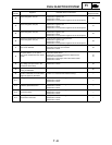
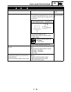
07
Vehicle speed pulse Displays the accumulation of the vehicle pulses that are gen-
erated when the tire is spun.
(0 ~ 999; resets to 0 after 999)
OK if the numbers appear on
the meter.
08
Lean angle cut-off
switch
Displays the lean angle cut-off switch values. Upright: 0.4 ~ 1.4 V
Overturned: 3.8 ~ 4.2 V
09
Fuel system voltage
(battery voltage)
Displays the fuel system voltage (battery voltage).
Engine stop switch is on.
0 ~ 18.7 V
Normally, approximately 12.0 V
20
Sidestand switch Displays that the switch is ON or OFF. (When the gear is in a
position other than neutral.)
Stand retracted: ON
Stand extended: OFF
21
Neutral switch Displays that the switch is ON or OFF. Neutral: ON
In gear: OFF
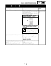
30
Ignition coil #1 After 1 second has elapsed from the time the engine stop
switch has been turned from OFF to ON, it actuates ignition
coil #1 for five times every second and illuminates the engine
trouble warning light.
* Connect an ignition checker.
* If the engine stop switch is ON, turn it OFF once, and then
turn it back ON.
Check that spark is generated,
5 times with the engine stop
switch ON.
31
Ignition coils #2 After 1 second has elapsed from the time the engine stop
switch has been turned from OFF to ON, it actuates ignition
coil #2 for five times every second and illuminates the engine
trouble warning light.
* Connect an ignition checker.
* If the engine stop switch is ON, turn it OFF once, and then
turn it back ON.
Check that spark is generated,
5 times with the engine stop
switch ON.