


47
posts and cable connectors with Grafo 112X (skin-over)
grease (Toro Part No. 505-47) or petroleum jelly to prevent
corrosion.
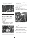
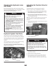
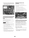
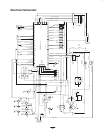
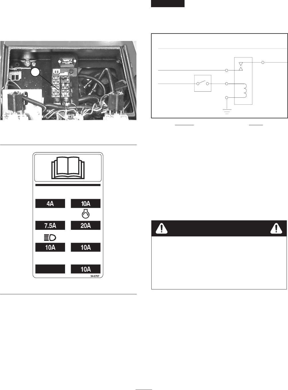
Fuses
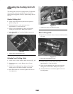
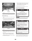
There are 4 fuses in the machines electrical system. They
are located below control panel (Fig. 71 and 72).
1
Figure 71
1. Fuses
Figure 72
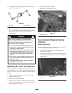
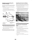
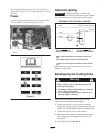
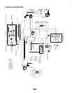
Optional Lighting
Important If optional lighting is be added to the
traction unit, use the following schematic and part numbers
to prevent damage to the traction units electrical system.
Switch
Relay
Orange
Red
Black
23
86
85
30
30
To Lights w/external ground
To Lights
SCHEMATIC FOR OPTIONAL LIGHTING
Switch* Relay
Toro Part No. 75–1010
Honeywell Part No. 1TL1–2
Toro Part No. 70–1480
Bosch Part No. 0–332–204
* Punch out in control panel provided for switch installa-
tion
Add 10 Amp fuse to fuse block at location shown
Black, red and orange wires are located in control con-
sole.
Note: Make sure a good ground is achieved to prevent
damage to traction unit.
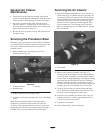
Backlapping the Cutting Units
Contact with the reels or other moving parts can
result in personal injury.
• Keep fingers, hands, and clothing away from the
reels or other moving parts.
• Never attempt to turn the reels by hand or foot
while the engine is running.
Warning
Note: When backlapping, the front units all operate
together, and the rear units operate together.
1. Position the machine on a level surface, lower the
cutting units, stop the engine, engage the parking brake,
and move the Enable/Disable switch to disable position.
2. Unlock and raise the seat to expose controls.
3. Make initial reel to bedknife adjustments appropriate
for backlapping on all cutting units which are to be
backlapped.
4. Start engine and run at idle speed.