


30
1
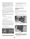
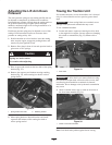
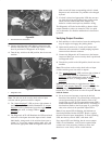
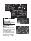
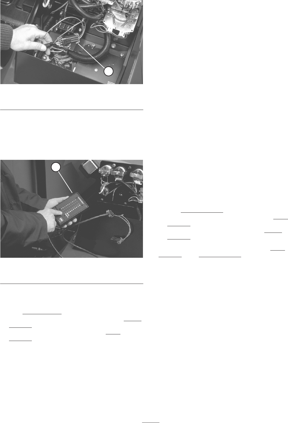
Figure 36
1. Wire harness and connectors
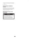
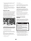
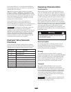
3. Connect the Diagnostic ACE display connector to the
harness connector (Fig. 37). Make sure correct overlay
decal is positioned on Diagnostic ACE display.
4. Turn the key switch to the ON position, but do not start
machine.
1
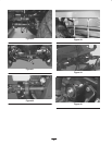
Figure 37
1. Diagnostic ACE
Note: The red text on the overlay decal refers to input
switches and the green text refers to outputs.
5. The “inputs displayed” LED, on lower right column of
the Diagnostic ACE, should be illuminated. If “outputs
displayed” LED is illuminated, press the toggle button,
on Diagnostic ACE, to change LED to “inputs
displayed”.
6. The Diagnostic ACE will illuminate the LED associated
with each of the inputs when that input switch is closed.
Individually, change each of the switches from open to
closed (i.e., sit on seat, engage traction pedal, etc.), and
note that the appropriate LED on Diagnostic ACE will
blink on and off when corresponding switch is closed.
Repeat on each switch that is it possible to be changed
by hand.
7. If switch is closed and appropriate LED does not turn
on, check all wiring and connections to switch and/or
check switches with an ohm meter. Replace any
defective switches and repair any defective wiring.
The Diagnostic ACE also has the ability to detect which
output solenoids or relays are turned on. This is a quick
way to determine if a machine malfunction is electrical or
hydraulic.
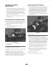
Verifying Output Function
1. Park machine on a level surface, lower the cutting units,
stop the engine and engage the parking brake.
2. Open control panel cover. Locate wire harness and
connectors near controller. Carefully unplug loopback
connector from harness connector.
3. Connect the Diagnostic ACE connector to the harness
connector. Make sure correct overlay decal is positioned
on Diagnostic ACE.
4. Turn the key switch to the ON position, but do not start
machine.
Note: The red text on the overlay decal refers to input
switches and the green text refers to outputs.
5. The “outputs displayed” LED, on lower right column of
Diagnostic ACE, should be illuminated. If “inputs
displayed” LED is illuminated, press the toggle button,
on Diagnostic ACE, to change LED to “outputs
displayed”.
Note: It may be necessary to toggle between “inputs
displayed” and “outputs displayed” several times to do the
following step. To toggle back and forth, press toggle
button once. This may be done as often as required. Do not
hold the button.
6. Sit on the seat and attempt to operate the desired
function of the machine. (If you need help verifying the
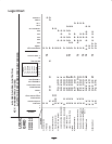
correct input settings for each function, refer to the
Logic Chart on page 32) The appropriate output LED’s
should illuminate to indicate that the ECU is turning on
that function. (Refer to the list on page 31, or the logic
chart to be certain of the specified output LED’s.
Note: If any output LED is blinking, this indicates an
electrical problem with that OUTPUT. Repair / replace
defective electrical parts immediately. To reset a blinking
LED, turn the key switch “OFF”, then back “ON”.
If no output LED’s are blinking, but the correct output
LED’s do not illuminate, verify that the required input
switches are in the necessary positions to allow that
function to occur. Verify correct switch function.