


29
3. Attach the other end of the towing device to a vehicle
that is capable of towing the machine safely and at
speeds below 3 mph.
4. An operator must be on the machine to steer it and keep
the traction pedal fully depressed in the forward
position while towing.
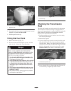
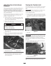
5. When towing is completed, reinstall driveshaft as
shown in Figure 33. The splines are designed to allow
assembly only when the two halves of the shaft are
properly oriented.
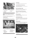
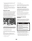
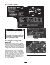
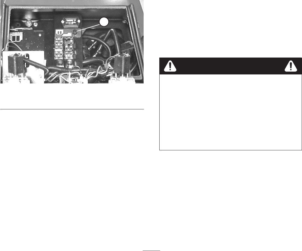
Diagnostic Light
The RM 5200-D/5400-D is equipped with a diagnostic light
which indicates if the electronic controller is functioning
correctly. The green diagnostic light is located under the
control panel, next to the fuse block (Fig. 35). When the
electronic controller is functioning correctly and the key
switch is moved to the ON position, the controller
diagnostic light will be illuminated. The light will blink if
the controller detects a malfunction in the electrical system.
The light will stop blinking and automatically reset when
the key switch is turned to the OFF position.
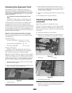
1
Figure 35
1. Electronic controller light
When the controller diagnostic light blinks, one of the
following problems has been detected by the controller:
• One of the outputs has been shorted.
• One of the outputs is open circuited.
Using the diagnostic display, determine which output is
malfunctioning; refer to Checking the Interlock Switches,
page 29.
If the diagnostic light is not illuminated when the key
switch is in the ON position, this indicates that the
electronic controller is not operating. Possible causes are:
• Loopback is not connected.
• The light is burned out.
• Fuses are blown.
• Not functioning correctly.
Check electrical connections, input fuses and diagnostic
light bulb to determine malfunction. Make sure loopback
connector is secured to wire harness connector.
Diagnostic ACE Display
The RM 5200-D/5400-D is equipped with an electronic
controller which controls most machine functions. The
controller determines what function is required for various
input switches (i.e. seat switch, key switch, etc.) and turns
on the outputs to actuate solenoids or relays for the
requested machine function.
For the electronic controller to control the machine as
desired, each of the input switches, output solenoids and
relays must be connected and functioning properly.
The Diagnostic ACE display is a tool to help the user verify
correct electrical functions of the machine.
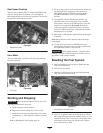
Checking the Interlock
Switches
The purpose of the interlock switches are to prevent the
engine from cranking or starting unless the traction pedal is
in NEUTRAL, the Enable/Disable switch is in DISABLE
and the Lower Mow / Raise control is in the neutral
position. In addition, the engine will stop when the traction
pedal is depressed with operator off the seat.
If safety interlock switches are disconnected or
damaged the machine could operate unexpectedly
causing personal injury.
• Do not tamper with the interlock switches.
• Check the operation of the interlock switches
daily and replace any damaged switches before
operating the machine.
• Replace switches every two years regardless of
whether they are operating properly or not.
Caution
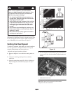
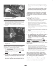
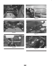
Verifying Interlock Switch Function
1. Park machine on a level surface, lower the cutting units,
stop the engine and engage the parking brake.
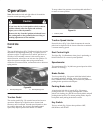
2. Open control panel cover. Locate wire harness and
connectors near controller (Fig. 36). Carefully unplug
loop back connector from harness connector.