


17
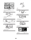
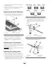
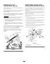
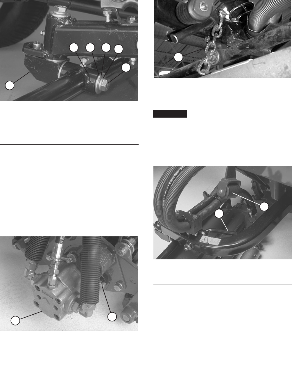
5. Align the mounting shaft of the cutting unit with the
pivot tube on the carrier frame. Insert the shaft into the
tube (Fig. 8).
1
2 3 4
5
6
Figure 8
1. Cutting unit mounting
shaft
2. Carrier frame pivot tube
3. Thrust washer
4. Flat washer
5. Lock washer
6. Capscrew
6. Secure shaft in pivot tube with a thrust washer, flat
washer, lock washer, and capscrew (Fig. 8).
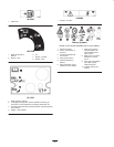
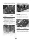
7. Assemble the mounting nuts for the reel drive motor to
each cutting unit (Fig. 9). Leave approximately 1/2 in.
of threads exposed on each mounting stud.
8. Coat the spline shaft of the motor with clean grease and
install the motor by rotating the motor clockwise so the
motor flanges clear the studs. Rotate the motor
counterclockwise until the flanges encircle the studs and
tighten the mounting nuts. Ensure that the washers are
against the nuts.
1
2
Figure 9
1. Reel drive motor 2. Mounting nuts
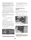
9. Detach chain from lift arm and secure it to cross tube on
each rear cutting unit with a capscrew, flat washer, and
locknut (Fig. 10).
1
Figure 10
1. Lock-up chain
Important Make sure that all hydraulic hoses are
routed away from cutting unit so when cutting unit pivots
excessive rubbing does not occur.
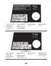
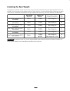
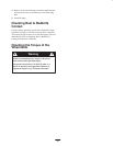
10. Check adjustment of lock-up rollers (Fig. 11). When
properly adjusted, they will contact the lock-up levers
on rear lift arms and support the cutting units when
fully raised.
1
2
Figure 11
1. Lock-up rollers 2. Lock-up levers
11. Mount a basket to each cutting unit carrier frame by
inserting basket mounting pin into basket bracket and
depressing opposite mounting pin into pivoting bracket.