


43
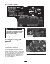
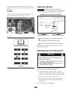
Adjusting the Cutting Unit Lift
Rate
The cutting unit lift circuit is equipped with (3) adjustable
valves used to ensure the cutting units do not raise too
quickly and bang against lift stops. Adjust cutting units as
follows:
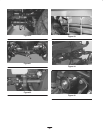
Center Cutting Unit
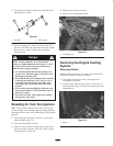
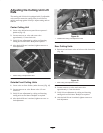
1. Locate valve behind access panel above operator’s
platform (Fig. 62).
2. Loosen setscrew on valve and rotate valve
approximately 1/2 turn clockwise.
3. Verify lift rate adjustment by raising and lowering
cutting unit several times. Readjust as required.
4. After desired lift rate is attained, tighten setscrew to
lock adjustment.
1
Figure 62
1. Center cutting unit adjustment valve
Outside Front Cutting Units
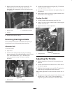
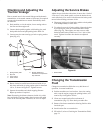
1. Locate valve on flow divider (under foot rest) (Fig. 63).
2. Loosen setscrew on valve. Rotate valve 1/2 turn
clockwise.
3. Verify lift rate adjustment by raising and lowering
cutting units several times. Readjust as required.
4. After desired lift rate is attained, tighten set screw to
lock adjustment.
1
Figure 63
1. Outside front cutting units adjustment valve
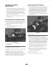
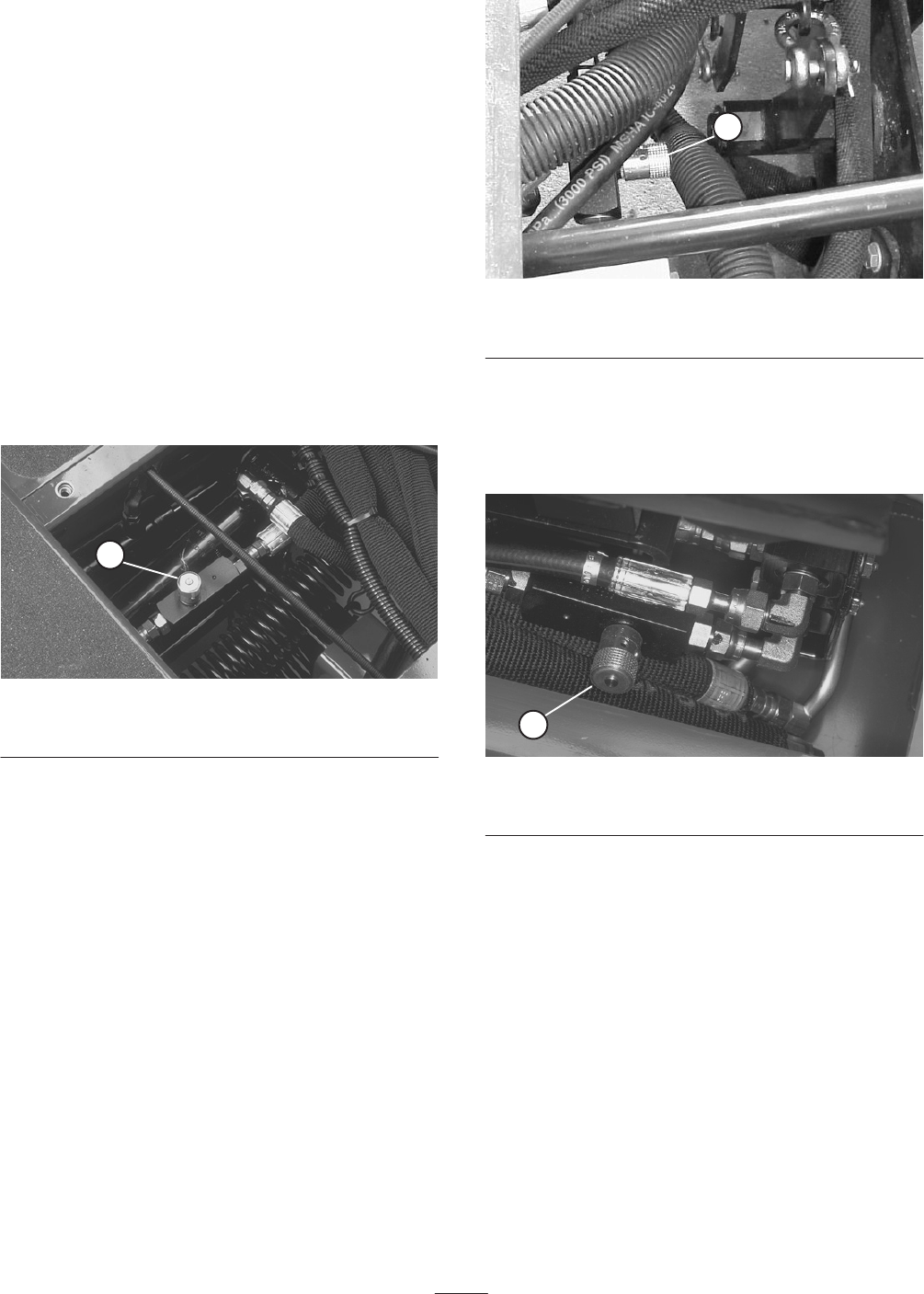
Rear Cutting Units
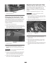
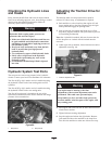
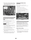
1. Raise hood and locate valve on left rear side of machine
(Fig. 64).
1
Figure 64
1. Rear cutting units adjustment valve
2. Loosen setscrew on valve and rotate valve
approximately 1/2 turn clockwise.
3. Verify lift rate adjustment by raising and lowering
cutting units several times. Readjust as required.
4. After desired lift rate is attained, tighten setscrew to
lock adjustment.