


42
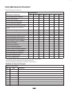
Checking the Hydraulic Lines
and Hoses
Daily, check hydraulic lines and hoses for leaks, kinked
lines, loose mounting supports, wear, loose fittings, weather
deterioration and chemical deterioration. Make all
necessary repairs before operating.
Hydraulic fluid escaping under pressure can
penetrate skin and cause injury.
• Make sure all hydraulic fluid hoses and lines are
in good condition and all hydraulic connections
and fittings are tight before applying pressure to
the hydraulic system.
• Keep your body and hands away from pin hole
leaks or nozzles that eject high pressure
hydraulic fluid.
• Use cardboard or paper to find hydraulic leaks.
• Safely relieve all pressure in the hydraulic
system before performing any work on the
hydraulic system.
• Get immediate medical help if fluid is injected
into skin.
Warning
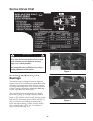
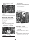
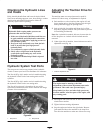
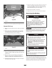
Hydraulic System Test Ports
The test ports are used to test pressure in the hydraulic
circuits. Contact your local Toro distributor for assistance.
Test Port #1 (Fig. 60) is used to assist in trouble shooting
the hydraulic circuit for the front cutting units and lift
cylinders.
Test Port #2 (Fig. 60) is used to assist in trouble shooting
the hydraulic circuit for the rear cutting units.
Test Port #3 (not shown) is located on the rear of the
hydrostatic transmission and is used to measure the charge
pressure of the transmission.
1
2
Figure 60
1. Test port #1 2. Test port #2
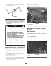
Adjusting the Traction Drive for
Neutral
The machine must not creep when traction pedal is
released. If it does creep, an adjustment is required.
1. Park machine on a level surface, shut engine off, and
lower cutting units to the floor. Depress only the right
brake pedal and engage the parking brake.
2. Jack up left side of machine until front tire is off the
shop floor. Support machine with jack stands to prevent
it from falling accidentally.
Note: On 4 wheel drive models, left rear tire must also be
off the shop floor or 4 wheel drive driveshaft must be
removed.
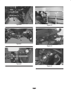
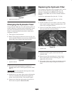
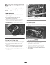
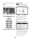
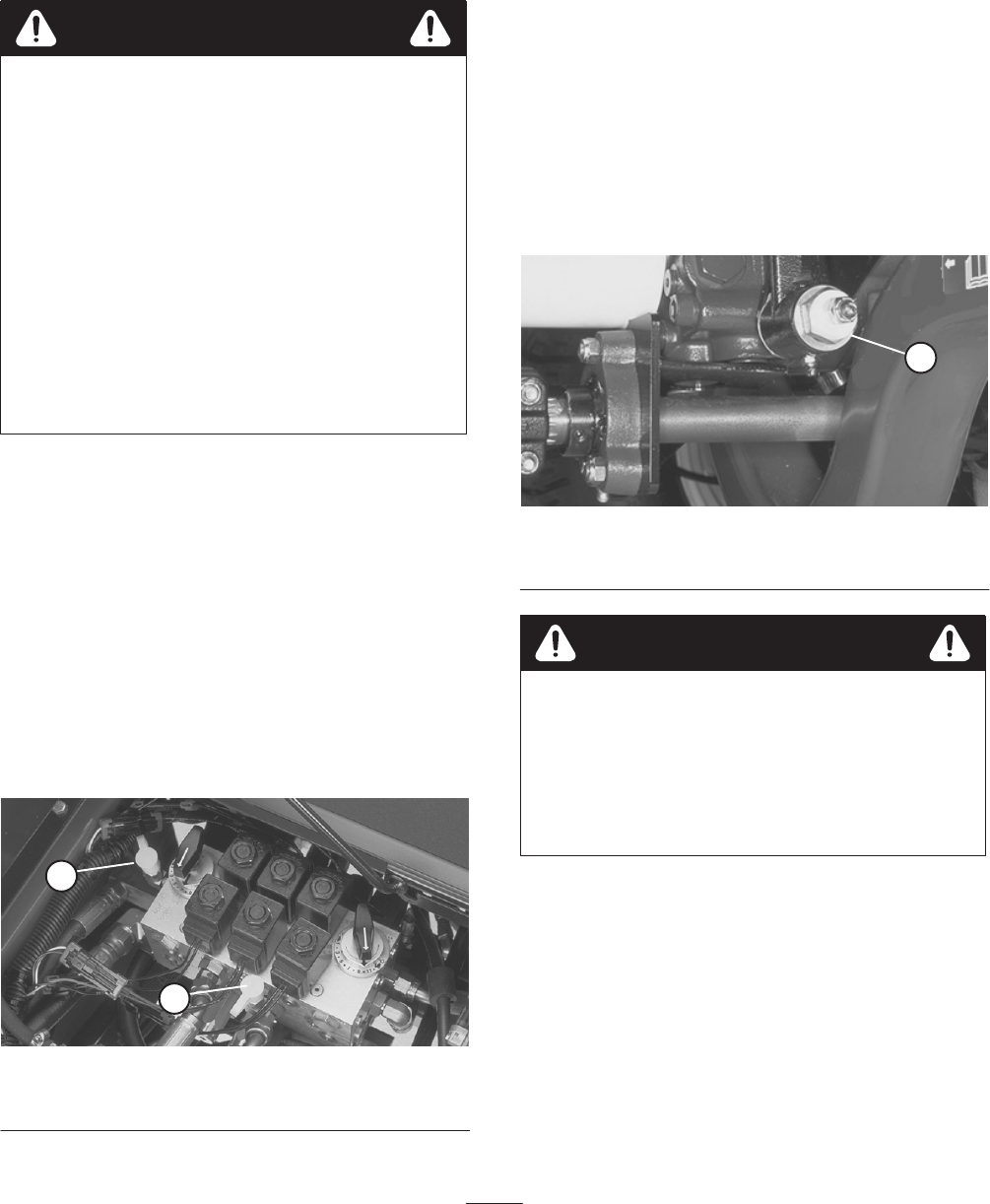
3. Under right side of machine, loosen locknut on traction
adjustment cam (Fig. 61).
1
Figure 61
1. Traction adjustment cam
The engine must be running so the final
adjustment of the traction adjustment cam can be
performed. This could cause personal injury.
Keep hands, feet, face, and other body parts away
from the muffler, other hot parts of the engine, and
any rotating parts.
Warning
4. Start engine and rotate cam hex in either direction until
wheel ceases rotation.
5. Tighten locknut securing adjustment.
6. Stop the engine and release the right brake. Remove
jack stands and lower the machine to the shop floor.
Test drive the machine to make sure it does not creep.