


Manual: 152-082010 301-305-306_303-307 Series Page 8 of 35
sulfur hexafluoride) or at high pressures (> 250 psig) the instrument must be installed horizontally.
When mounted in a different orientation the instrument should be re-zeroed at zero flow with the
system pressurized to the expected operating pressure.
One of the smallest of the internal passageways in the 300 Series is the diameter of the sensor tube,
which can be 0.026” (0.66 mm), 0.017” (0.43mm), or 0.014” (0.36mm), so the instrument requires
adequate filtering of the gas supply to prevent blockage or clogging of the tube.
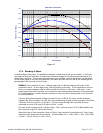
The pressure regulator and the plumbing upstream must be of sufficient size to minimize changes in the
upstream pressure. When switching from full flow to zero flow, the inlet pressure of instrument should
rise to no more that 30% above the inlet pressure at full flow. In general, high capacity regulators and
large internal diameter plumbing help to make the system more stable. The pressure drop between the
regulator and the instrument due to line resistance should be minimized.
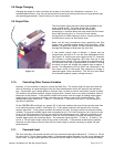
There are two threaded holes located on the bottom of the base that can be used to secure it to a
mounting bracket, if desired. Other holes for special mounting can be added if desired.
The optional inlet and outlet fittings for the 301/303 are 0.5”, 0.75” Swagelok, 0.5” VCR and 0.5” VCO
fittings. The O-rings for the end cap are Viton (optional Kalrez, Neoprene or Buna-N). The HFM-305 and
HFC-307 are provided with 1” Swagelok, VCR or VCO fittings. The HFM-306 can have 1” or 2” Swagelok
fittings. It is suggested that all connections be checked for leaks after installation. This can be done by
pressurizing the instrument (do not exceed pressure rating of the instrument) and applying a diluted
soap solution to the flow connections.
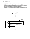
2.5. Electrical Connections
DANGER: Care must be taken to avoid high voltages that may be present when dealing
with power supplies.
If a power supply from Hastings Instruments is used, installation consists of connecting the 300 Series
cable from the “D” connector on the rear of the power supply to the “D” connector on the top of the
flow meter/controller. The “H” pin-out requires cable AF-8-AM (grey molded back shell). The “U” pin-
out requires cable # 65-791 (black molded back shell).
If a different power supply is used, follow the instructions below when connecting the flow meter and
refer to either table 2.1 or 2.2 for the applicable pin-out. The power supply used must be bipolar and
capable of providing ±15 VDC at 55 mA for flow meter applications and ±15 VDC at 150 mA for
controllers. These voltages must be referenced to a common ground. One of the “common” pins of the
Hastings instrument must be connected to the common terminal of the power supply. Case ground of
the instrument should be connected to the AC ground locally. The cable shield (if available) should be
connected to AC ground at the either the power supply end, or the instrument end of the cable, not at
both. Pin 6 is the output signal from the flow meter. The standard output will be 0 to 5 VDC, where 5
VDC is 100% of the rated or full scale flow.
The command (set point) input should be a 0 - 5 VDC signal (or 4 - 20mA if configured as such), and must
be free of spikes or other electrical noise, as these would generate false flow commands that the
controller would attempt to follow. The command signal should be referenced to signal common.
A valve override command is available to the flow controller. Connect the center pin of a single pole,
three-position switch (center off) to the override pin. Connect +15 VDC to one end of the three position
switch, and -15 VDC to the other end. The valve will be forced full open when +15 VDC is supplied to the
override pin, and full closed when -15 VDC is applied. When there is no connection to the pin (the
three-position switch is centered) the valve will be in auto control, and will obey the 0 - 5 VDC
commands supplied to command (set-point) input.
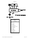
Figure 2-1 and Table 2-1 show the 300 Series “H” pin out.
Figure 2-2 and Table 2-2 show the 300 Series U” pin out.