


Manual: 152-082010 301-305-306_303-307 Series Page 16 of 35
2.8. Range Changing
Changing the range of a flow controller can be done in the field, but calibration is required. It is
recommended however, that the unit be sent back to the factory along with the new range desired, gas
and operating parameters. Consult factory for more information.
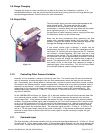
2.9. Output Filter
The flow output signal may have noise superimposed on the
mean voltage levels. This noise may be due to high
turbulence in the flow stream that the fast sensor is
measuring or it could be electrical noise when the flow meter
has a high internal gain (i.e. 5 sccm full scale meter).
Varying levels of radio frequency noise or varying airflow over
the electronics cover can also induce noise.
Noise can be most pronounced when measuring the flow
output with a sampling analog/digital (A/D) converter. When
possible, program the system to take multiple samples and
average the readings to determine the flow rate.
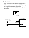
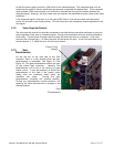
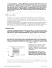
If less overall system noise is desired, a jumper may be
installed over the pins of JP-1 on the flow measurement card.
See Figure 2-8. Covering the pins closest to the “D” connector
will activate a resistor-capacitor (RC) filter that has a time
constant of one second. This will change the settling time of
the indicated flow rate to approximately 4 seconds. Covering
the other two pins will change the response time to approx. 1
second. This adjustment will not affect the calibration of the
flow meter circuit or the actual flow response to change in
command signal (flow controllers). This will only slow down
the indicated response (output voltage/current).
2.10. Controlling Other Process Variables
Normally, a flow controller is setup to control the mass flow. The control loop will open and close the
valve as necessary to make the output from the flow measurement match the input on the command
line. Occasionally, gas is being added or removed from a system to control some other process variable.
This could be the system pressure, oxygen concentration, vacuum level or any other parameter which is
important to the process. If this process variable has a sensor that can supply an analog output signal
proportional to its value then the flow controller may be able to control this variable directly. This
analog output signal could be 0 - 5 Volts, 0 - 10 Volts (or 4 - 20 mA for units with 4 - 20 mA boards) or
any value in between.
On the CONTROLLER card there is a jumper (JP-1) that sets whether the control loop controls mass flow
or an external process variable. See Figure 2-9. If the jumper connects the top two pins, the loop
controls mass flow. If the jumper connects the bottom two pins, the loop controls an external process
variable. This process variable signal must be supplied on pin 13 of the D-connector (for H pin out units)
or pin 12 of the D-connector (for U pin out units) of the measurement card. When the controller is set
for external variable control it will open or close the valve as necessary to make the external process
variable signal match the command signal. The command signal may be 0 - 5 Volts, 0 - 10 Volts (4 - 20
mA for 4 - 20 mA input/output cards) or any value in between. If the process variable has a response
time that is much faster or slower than the flow meter signal it may be necessary to adjust the gain
potentiometer.
2.11. Command Input
The flow controller will operate normally with any command input signal between 0 - 10 Volts (4 - 20 mA
for units with 4 - 20 mA input/output cards). If the command signal exceeds ±14 volts it may damage the
circuit cards. During normal operation the control loop will open or close the valve to bring the output
Figure 2-8