


Manual: 152-082010 301-305-306_303-307 Series Page 17 of 35
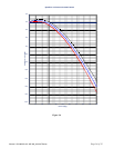
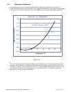
of the flow meter signal to within ± 0.001 Volts of the command signal. The command signal will not
match the flow signal if there is insufficient gas pressure to generate the desired flow. If the command
signal exceeds 5 Volts the controller will continue to increase the flow until the output matches the
command signal. However, the flow output may not maintain the published accuracy values under these
conditions.
If the command signal is less than 1% of full scale (0.05 Volts or 4.16 mA) the valve override control
circuit will activate in the closed position. This will force the valve completely closed regardless of the
flow signal.
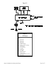
2.12. Valve Override Control
The valve override control line provides a method to override the loop controller and open or close the
valve regardless of the flow or command signals. During normal operation this line must be allowed to
float freely. This will allow the loop control to open and close the valve as it requires. If the valve
override line is forced high (> +5 Volts) the valve will be forced full open. If the valve overrides line is
forced negative (< -5 Volts) the valve will be forced closed.
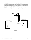
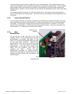
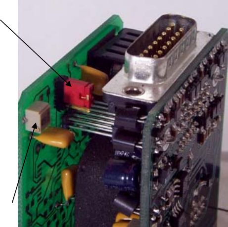
2.13. Gain
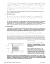
Potentiometer
On the top left of the inlet side of the flow
controller there is a hole through which the gain
potentiometer is accessible. See Figure 2-9 and
Figure 4-2. This gain potentiometer affects the gain
of the closed loop controller. Normally this
potentiometer will be set at the factory for good
stable control. It may be necessary to adjust this
potentiometer in the field if the system varies
widely from the conditions under which the
controller was setup. Turning this gain
potentiometer clockwise will improve stability.
Turning the potentiometer counter-clockwise will
speed up the valve reaction time to changes in the
command signal.
Figure 2-9
Control Loop
Jumper
Gain
Potentiometer