


Manual: 152-082010 301-305-306_303-307 Series Page 22 of 35
()
ΔP
LQ
D
Q
D
KK
ce
=+ +
128 8
4
2
24
μ
π
ρ
π
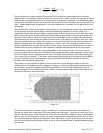
The end effects for a typical laminar flow element in air account for approximately 4% of the total
pressure drop. For hydrogen, however, which has a density that is about 14 times less than air and has a
viscosity that is much greater than air, the second term is completely negligible. For the heavier gasses
such as sulfur hexafluoride which has a density 5 times that of air the end effects will become 10% of the
total. These changes make it impossible to accurately calibrate an instrument on one gas and use it for
another gas.
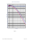
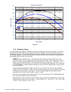
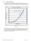
The pressure drop is linear with respect to the volumetric flow rate between a point that is downstream
of the entrance area and another point further downstream but upstream of the exit region. For a
typical flow divider tube the entry length is approximately 0.16 cm. From this it can be seen that if the
sensor inlet pickup point is inside of the flow divider tube but downstream of the entrance length and if
the sensor outlet point is inside the flow divider tube but upstream of the exit point then the pressure
drop that drives the flow through the sensor would be linear with respect to volumetric flow rate. Since
the pressure drop across the sensor now increases linearly with the main flow rate and the sensor has a
linearly increasing flow with respect to pressure drop, there is now a flow through the sensor which is
directly proportional to the main flow through the flow divider, without the flow division errors that are
present when the sensor samples the flow completely upstream and downstream of the flow divider.
Unfortunately, a typical shunt has an internal diameter on the order of 0.3 mm. This is too small to
insert tap points into the tube. Also, the sample flow through the sensor is approximately 10 sccm while
the flow through a shunt is approximately 25 sccm. This means the sample flow would be affecting the
flow it was trying to measure. If the sensor tube is made large enough, and with enough flow through it
to insert the sensor taps at these positions, then the pressure drop would be too small to push the
necessary flow through the sensor tube.
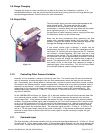
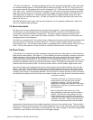
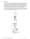
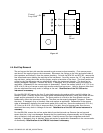
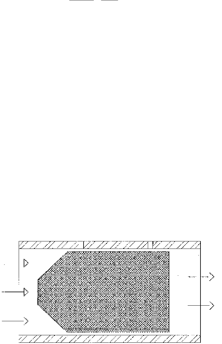
The solution is to use a different geometry for the flow tube. It must be large enough to allow the
sample points in the middle yet with passages thin enough to create the differential pressures required
for the sensor. An annular passage meets these requirements. All of the 400 I series shunts have an
annular passageway that passes between the outside of the main shunt body and the inside edge of the
base where the sensor taps are located.
Figure 3-2
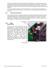
The shunt must generate a pressure drop at the desired full scale flow which drives the proper flow
through the sensor tube to generate a full scale output from the sensor. Since the full scale flow of the
sensor is the same for all of the different full scale flows that may pass through the shunt, the geometry
must vary for the different full scale flows in order to generate the same pressured drop for all of them.
This is accomplished by adding more channels to main shunt body. As the full scale flow rate increases
the flow meter body must get larger to allow room for the increased number of bypass passageways that
are required.