


Manual: 152-082010 301-305-306_303-307 Series Page 25 of 35
4. Maintenance
4.1. Authorized Maintenance
With proper care in installation and use, the flow meter will require little or no maintenance. If
maintenance does become necessary, most of the instrument can be cleaned or repaired in the field.
Some procedures may require recalibration. Do not attempt these procedures unless facilities are
available. Entry into the sensor or tampering with the printed circuit board will void warranty. Do not
perform repairs on these assemblies while the unit is still under warranty.
CAUTION: Some parts of the instrument are delicate and other parts are heavy enough
to cause an injury if dropped. Use extreme care when servicing the instrument. The
potentiometer positions and the electrical components referred to in the
troubleshooting section can be found in Section 4.3.
4.2. Troubleshooting
Symptom: Output reads strong indication of flow with no flow present. Zero pot has no effect.
Cause: Power shorted out.
Action: Turn the power supply off for a few seconds then turn it on again. If this is ineffective,
disconnect the power supply from the unit. Check that the power supply voltages are
correct. Incorrect voltages most likely signify a faulty regulator chip inside the supply.
If the power supply display returns to zero after the instrument has been disconnected
there may be a short from the unit to ground.
Symptom: 300 Series instrument output continues to indicate flow with no flow present, or
indicates ±14 volts. Power supply inputs are correct (see the above troubleshooting tip)
and zero pot has no effect.
Cause: Faulty IC chip(s) on the main PC board.
Action: Replace main PC board. (See Section 4.5)
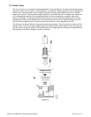
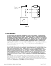
Symptom: Output of flow meter is proportional to flow,
but extremely small and not correctable by span pot.
Cause: Sensor is not being heated.
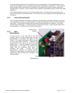
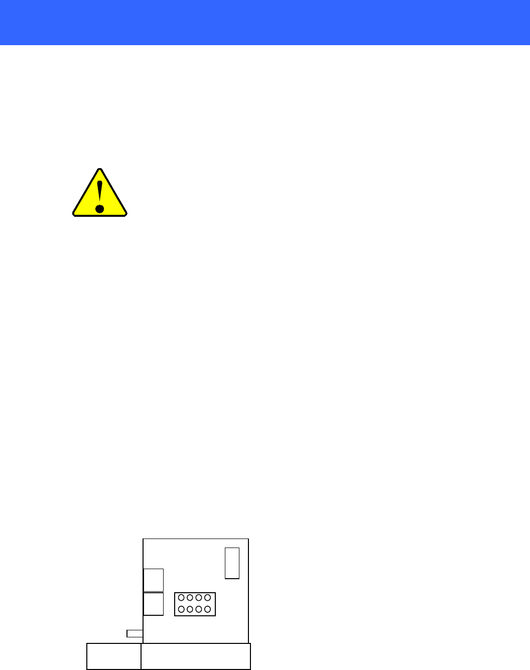
Action: Shut off gas supply and disconnect the power to
the flow meter. Remove cover and PC board from unit.
Check the resistance from pins 1 to 2 and 3 to 4 of the
sensor module. Both sets of pins should read
approximately the same value between 1 and 2 k
Ω
nominal resistance. Also check that the resistance from
pins 5 to 6, and 7 to 8 are both nearly the same value
between 200 and 400
Ω. See Figure 4-1. Incorrect
resistance values indicate that the sensor unit needs to
be replaced.
Figure 4-1
5 6 7 8
4 3 2 1