


Manual: 152-082010 301-305-306_303-307 Series Page 28 of 35
4.5. Printed Circuit Board and Sensor Replacement
NOTE: This instrument contains static sensitive PC boards. Maintain static protection when handling the
PC boards.
In the event that any of the PC boards fail, they are easily removed from the instrument and replaced
with a spare. It is recommended that the metering printed circuit board and sensor be replaced as a unit
because they are electronically matched to optimize response time. The sensor can also be removed
easily. This ease in disassembly and replacement substantially reduces instrument downtime.
1. Replacement of the 4 - 20 mA option PC board: Unplug the power cable from the instruments “D”
connector. Remove the fasteners and steel can. The 4 - 20 mA board is the PC board mounted by a
single screw. Remove the screw and lift off the 4 - 20 mA board. Be careful not to damage the main
board and 4 - 20 mA board connector.
2. Replacement of the main PC board: Unplug the power cable from the instruments “D” connector.
Remove the fasteners and steel can. Remove the 2 screws which fasten the main PC board to the sensor
module. Gently unplug the main board from the sensor (and from the 4 - 20 mA board, if present).
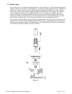
3. Replacement of the flow sensor: Remove the PC board(s) as described above. Remove the four (4)
Allen head cap screws that fasten the sensor to the main instrument base. Remove the sensor module
from the base, discarding the used nickel gaskets. New nickel gaskets are required for re-assembly.
To place an order or to obtain information concerning replacement parts, contact the factory
representative in your area. See section 6 in this manual for the address or phone number. When
ordering, include the following information: Instrument model number, part description and Hastings
part number.