


Manual: 152-082010 301-305-306_303-307 Series Page 27 of 35
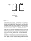
4.4. End Cap Removal
The end cap on the inlet side must be removed to gain access to shunt assembly. First remove power
and shut off the supply of gas to the instrument. Disconnect the fittings on the inlet and outlet sides of
the transducer and remove it from the system plumbing. On both the HFM-301 and HFC-303, remove the
four Allen head screws holding the end cap to the instrument. Carefully remove the “O”-ring sealed end
cap and shunt, noting their order and the proper annular orientation of the shunt. The shunt position is
critical to the flow dynamics and can substantially affect the instrument linearity. The shunt can be
severely damaged if dropped. Examine the shunt. If damaged, dirty or blocked, clean and replace as
applicable. Reassemble in the reverse order of disassembly. Secure the endcap with 65 in lb. (7.3 N.m)
to 85 in lb (9.6 N-m) of torque on each high-tensile socket head cap screw. Use of a fastener other than
the one mentioned here may result in leakage at the seal. Recalibration of the 301/303 series
instrument is necessary.
For the HFM-305/307 remove the four 12 point bolts securing the endcap while carefully holding the
endcap in place. Carefully remove the metal gasket sealed endcap and shunt, noting their order and the
proper annular orientation of the shunt. The shunt position is critical to the flow dynamics and can
substantially affect the instrument linearity. The shunt can be severely damaged if dropped. Examine
the shunt. If damaged, dirty or blocked, clean and replace as applicable. Reassemble in the reverse
order of disassembly replacing the used metal gasket with a new one. Secure the endcap with 35 ft lb. (
47.5 N.m) to 40 ft lb. (54.3 N.m) of torque on each 12 pt bolt. Use of a fastener other than the one
mentioned here may result in leakage at the seal. Recalibration of the 305/307 series instrument is
necessary.
For the HFM-306, remove the six hex socket bolts from the inlet end cap. Remove the end cap and
ensure that the o-ring is not damaged. Remove the flow conditioning screen assembly and if damaged,
dirty or blocked, clean and replace as applicable. Carefully remove the flow straightener and shunt
assembly. If damaged, dirty or blocked, clean and replace as applicable. Reassemble in the reverse order
of disassembly. Recalibration of the HFM-306 instrument is necessary.
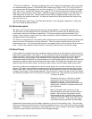
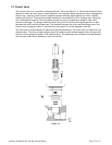
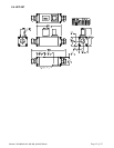
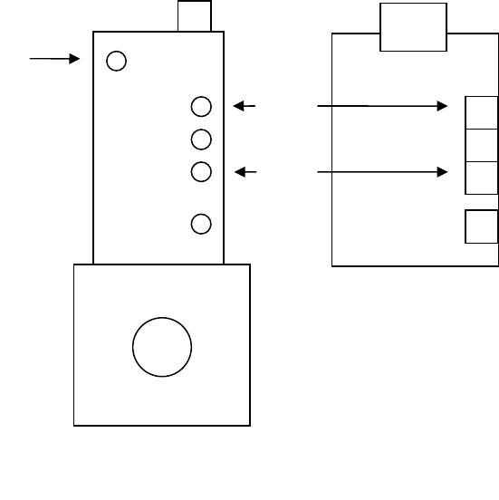
Figure 4-2
Zero
Span
Control
Loop Gain
PC
Board